REPAIRING AND NOT THROWING AWAY

Richtige Fernseher haben Röhren!

Richtige Fernseher haben Röhren!

In Brief: On this site you will find pictures and technical information about Service Modes, Circuit Diagrams, Firmware Update procedure, Disassemble procedure, Universal remote control set-up codes, Troubleshooting and more....

If you go into the profession, you will obtain or have access to a variety of tech tips databases HERE IT IS Master Electronics Repair !.

These are an excellent investment where the saying: 'time-is-money' rules. However, to learn, you need to develop a general troubleshooting approach - a logical, methodical, method of narrowing down the problem. A tech tip database might suggest: 'Replace C536' for a particular symptom. This is good advice for a specific problem on one model. However, what you really want to understand is why C536 was the cause and how to pinpoint the culprit in general even if you don't have a service manual or schematic and your tech tip database doesn't have an entry for your sick TV or VCR.

While schematics are nice, you won't always have them or be able to justify the purchase for a one-of repair. Therefore, in many cases, some reverse engineering will be necessary. The time will be well spent since even if you don't see another instance of the same model in your entire lifetime, you will have learned something in the process that can be applied to other equipment problems.
As always, when you get stuck, checking out a tech-tips database may quickly identify your problem and solution.In that case, you can greatly simplify your troubleshooting or at least confirm a diagnosis before ordering parts.

Happy repairing!
Today, the West is headed for the abyss. For the ultimate fate of our disposable society is for that society itself to be disposed of. And this will happen sooner, rather than later.

How to use the site:

- If you landed here via any Search Engine, you will get what you searched for and you can search more using the search this blog feature provided by Google. You can visit more posts scrolling the left blog archive of all posts of the month/year,
or you can click on the main photo-page to start from the main page. Doing so it starts from the most recent post to the older post simple clicking on the Older Post button on the bottom of each page after reading , post after post.

You can even visit all posts, time to time, when reaching the bottom end of each page and click on the Older Post button.

- If you arrived here at the main page via bookmark you can visit all the site scrolling the left blog archive of all posts of the month/year pointing were you want , or more simple You can even visit all blog posts, from newer to older, clicking at the end of each bottom page on the Older Post button.
So you can see all the blog/site content surfing all pages in it.

- The search this blog feature provided by Google is a real search engine. If you're pointing particular things it will search IT for you; or you can place a brand name in the search query at your choice and visit all results page by page. It's useful since the content of the site is very large.

Note that if you don't find what you searched for, try it after a period of time; the site is a never ending job !

..............The bitterness of poor quality is remembered long after the sweetness of todays funny gadgets low price has faded from memory........ . . . . . .....
Don't forget the past, the end of the world is upon us! Pretty soon it will all turn to dust!

©2010, 2011, 2012, 2013, 2014 Frank Sharp - You do not have permission to copy photos and words from this blog, and any content may be never used it for auctions or commercial purposes, however feel free to post anything you see here with a courtesy link back, btw a link to the original post here , is mandatory.
All posts are presented here for informative, historical and educative purposes as applicable within fair use. NOTHING HERE IS FOR SALE !

Showing posts with label ZENITH. Show all posts

Tuesday, 19 March 2019

HOW TO UNLOCK THE CHILD LOCK / KEY LOCK TO A ZENITH TELEVISION

HOW TO UNLOCK THE CHILD LOCK / KEY LOCK TO A ZENITH TELEVISION


UNLOCK PROCEDURES

Child Lock

  • Tune the television to a channel blocked by a child lock.  The words {Enter Lock Code} will be displayed on screen with four dashes underneath.
  • Press the numbers on the remote control to enter the child lock pass code to unlock the TV.  When the code is entered correctly, the blocked channel becomes visible.  The words {Enter Lock Code} remain on screen if password is not correct.
  • Enter ‘0000’ if you did not change the password on the TV, prior to enabling the child lock feature.  This number is the default pass code for the child lock.
  • Push ‘7777’ if you have changed the pass code for TV, but not remember the code. This number allows you to bypass the child lock and watching the program.
Key Lock
  • Press the ‘Menu’ button on the remote control to access the ‘Main Menu’ screen.
  • Scroll to ‘Special’ using the or button and press the button to access the ‘Special’ sub-menu.
  • Push the or button to hightlight “Key Lock” and then press button.
  • Press / button to change ‘Key Lock’ to “NO”, and press the “Menu” button to Save the Settings.

Friday, 15 March 2019

ZENITH PROJECTION TV_HOW TO DISCONNECT HV CONNECTOR_ IQC60H94W_IQC50H94W_IQC60H95W_IQC50H95W

ZENITH PROJECTION TV_HOW TO DISCONNECT HV CONNECTOR_ IQC60H94W_IQC50H94W_IQC60H95W_IQC50H95W


CAUTIONS
Perform the following when the HV connector (anode connector) is removed or inserted for CPT replacement, etc.
  • Roll out silicon cover from FBT’s contact area slowly.
  • While turning the connector about 90 degrees following the arrow (0 position). Push the connector slightly toward the case.
Remove the connector slowly by pulling it away from the case.
  • Refer to direction for insertion as shown in Fig above (L position). Insert connector until “CLICK” sound is heard.
  • Make sure the connector is pressed right in, so that it has a good contact with the spring.
  • Confirm the contact by pulling the connector slightly. (Don’t pull hard because it may damage the connector).
  • Cover the high voltage output by carefully pushing silicon boot onto it. (Don’t turn the connector).
Make sure the silicon boot is covering the high voltage output.
High Voltage limiter circuit check
  • Turn off TV and connect jig as shown in Figure. Adjust jig fully counter clockwise for minimum resistance.
  • Set the AC input to 120V AC and turn on TV.
  • Confirm test pattern on CRT is a usable picture, then slowly adjust jig until the picture disappears and TV shuts down.
  • When the limiter circuit is operating properly, Voltage will be less than 36.5kV at 0.6mA when TV shuts down.
  • Turn off set immediately after checking circuit operations.
  • Unplug set for one minute to reset shut-down circuit.  Remove jig and voltmeter.
Remove RH 80 and connect 50K Ohm jig as shown.

ZENITH - IQC60H94W_IQC50H94W_IQC60H95W_IQC50H95W TROUBLESHOOTING CHART

ZENITH - IQC60H94W_IQC50H94W_IQC60H95W_IQC50H95W

TROUBLESHOOTING CHART - 

TROUBLESHOOTING
No Raster
CLICK ON THE PICTURES TO ZOOM
POWER / DEFLECTION P.W.B
SMALL SIGNAL P.W.B

PROJECTION TV_ZENITH_ST-BY POWER SUPPLY SHUT-DOWN CAUSES & DEFLECTION_ SCHEMATIC [CIRCUIT DIAGRAM]

PROJECTION TV_ZENITH_ST-BY POWER SUPPLY Shut-Down Causes & DEFLECTION_ SCHEMATIC [Circuit Diagram]


DEFLECTION CIRCUIT
ST-BY POWER SUPPLY CIRCUIT
POWER SUPPLY SHUTDOWN EXPLANATION
Shut down occurs when the shutdown SCR QP01 is activated by gate voltage. When QP01 receives gate voltage of 0.6V, the SCR fires and give a ground path for the pin (5) of Connector PQD2 called PROTECT. This Low is routed to the Sub Power Supply PWB and is impressed on the base of the Relay Driver Transistor Q911 turning it Off. When Q911 turns Off the Relay S901 will disengage and remove the AC source from the Deflection Power Supply.
VOLTAGE LOSS DETECTION
1. Shorted 220V (DP31 and DP32) Inverted by QP03 then through DP22 The cathode of DP31 is connected directly to the 220V line. If it shorts this circuit is activated and pulls the base of QP03 low. This output High is routed through DP22 to the gate of the Shut Down SCR QP01.
2. Shorted SW+8V (DP33) Inverted by QP03 then through DP22 The cathode of DP33 is connected directly to the SW+8V line. If it shorts this circuit is activated and pulls the base of QP03 low. This output High is routed through DP22 to the gate of the Shut Down SCR QP01.
3. Shorted 28V (DP30) Inverted by QP03 then through DP22 The cathode of DP30 is connected directly to the 28V line. If it shorts this circuit is activated and pulls the base of QP03 low. This output High is routed through DP22 to the gate of the Shut Down SCR QP01.
4. Shorted Side Pin Cushion Circuit (D760 and Q754) then through DP34 The Side Pin Cushion circuit is comprised of I651, Q652 through Q657 If a problem occurred in this circuit that creates a Low on the cathode of D760, the low will be routed to the base of Q754, turning it
Off. This output High is routed through DP34 to the gate of the Shut Down SCR QP01.
5. Shorted Deflection Transformer or Misoperation (D756 and Q754) then through DP34 The Deflection circuit generates the actual Drive signal used in the High Voltage section. If a problem occurs in this circuit, the CRTs could be damaged or burnt. D757 is connected to D759 which is normally rectifying pulses off the Deflection Transformer T753. This rectified voltage is normally sent through D757, D756 to the base of Q754 keeping it On and it’s collector Low. If the Deflection circuit fails to produce the pulses for rectification, the base voltage of Q754 disappears and the transistor turns Off generating a High on its collector. This output High is routed through DP34 to the gate of the Shut Down SCR QP01.
6. Heater Loss Detection (DH26, DH27,QH07 and DP34).  This voltage does not go to the CRTs.The Flyback Transformer TH01 generates a pulse called Heater. (Note: This does not go to the CRTs as heater voltage, it’s used for Excessive High Voltage Detection. If a problem occurs
in this circuit, the Excessive High Voltage Detection circuit wouldn’t operate. It would be possible for there to be High Voltage but the circuit detecting Excessive High Voltage couldn’t work. DH26 is connected to DH24 which is normally rectifying pulses off the Flyback Transformer TH01. This rectified voltage is normally sent through DH26, DH27 to the base of QH07 keeping it On and its collector Low. If the Heater Pulse fails to produce the pulses for rectification, the base voltage of Q754 disappears and the transistor turns Off generating a High on its collector. This output High is routed through DH30 to the anode of DP34 to the gate of the Shut Down SCR QP01.
NEGATIVE VOLTAGE LOSS DETECTION:
7. -M28V Loss Detection (DP23, DP24) RP31 (18K ohm) is connected to the negative –M28V line and RP30 (22Kohm) is connected to the positive +29V line. The Cathode of DP23 monitors the neutral point where these two resistors are connected. If the negative voltage disappears, the zener DP23 fires. This high is routed through DP24 to the gate of the Shut Down SCR QP01 and Shut Down occurs.
8. SW-8V Loss Detection (DP28, DP29) RP26 (3.3K ohm) is connected to the negative SW-8V line and RP25 (3.3Kohm) is connected to the positive SW+8V line. The Cathode of DP28 monitors the neutral point where these two resistors are connected. If the negative voltage disappears, the zener DP28 fires. This high is routed through DP29 to the gate of the Shut Down SCR QP01 and Shut Down occurs.
EXCESSIVE CURRENT DETECTION:
9. 120V Deflection Power Supply (RP17, QP02, DP15, DP16 and DP18) If an excessive current condition of the Deflection B+ is detected by RP17 a 0.47 ohm resistor, the base of QP02 would drop. This would turn on QP02 and the high produced at the collector would fire zener DP15. This High would be routed through DP16 through DP18 to the gate of the Shut Down SCR QP01 and Shut Down occurs.
10. 28V Vertical IC I601 Power Supply (R645, Q609, D615, and DP34) If an excessive current condition of the Vertical B+ is detected by R645 a 0.68 ohm resistor, the base of Q609 would drop. This would turn on Q609 and the high produced at the collector would be routed through D615 through DP34 to the gate of the Shut Down SCR QP01 and Shut Down occurs.
VOLTAGE TOO HIGH DETECTION:
11. Excessive High Voltage Detection (DH31, RH54, RH55 and DH24). Sensed from the Heater Voltage generated from pin (5) of the Flyback Transformer TH01. Also, (DH42) sends a high command to the Horizontal Driver IC IH02, to defeat Horizontal Drive Output The Flyback
Transformer TH01 generates a pulse called Heater. (Note: This does not go to the CRTs as heater voltage, its used for Excessive High Voltage Detection). If this voltage goes too high indicating an excessive High Voltage condition, the voltage divider comprised of RH54 and RH55 would impress a high on the cathode of DH31.  This high is routed through DH34 to the gate of the Shut Down SCR QP01 and a Shut Down occurs.
12. Side Pincushion failure generating a High. (D754, and D753) The Side Pin Cushion circuit is comprised of I651, Q652 through Q657 If a problem occurred in this circuit that creates a High on the cathode of D754, the High will be routed through D753 to the gate of the Shut Down SCR QP01.
13. Deflection B+ Too High. (DP17, RP21 and RP22 RP21 and RP22 form a voltage divider. The top side of RP22 is monitored by DP17. If this voltage goes too high, zener DP17 will fire. This high is routed through DP18 to the gate of the Shut Down SCR QP01 and Shut Down
occurs.
14. Heater Voltage from the Deflection Power Supply Too High Detection. (DP27 and DP28) The Heater Voltage for the CRTs filament is generated in the Deflection Power Supply. This voltage is monitored by DP27. If this voltage goes too high, zener DP27 will fire. This high is routed through DP28 to the gate of the Shut Down SCR QP01 and Shut Down occurs.

ZENITH IQC60H94W_ IQC50H95W - CONVERGENCE POWER SUPPLY _ SCHEMATIC DIAGRAM [CIRCUIT DIAGRAM] _ [STK 392-110]

ZENITH IQC60H94W_ IQC50H95W - CONVERGENCE POWER SUPPLY _ SCHEMATIC DIAGRAM [Circuit Diagram] _ [STK 392-110]


CONVERGENCE SCHEMATIC
(CLICK ON THE SCHEMATIC TO MAGNIFY)
CONVERGENCE ADJUSTMENT (DIGITAL SETUP)
  • To enter this adjustment mode, press the front panel DIGITAL SETUP button.
  • Press the ARROW buttons on the remote control to move the displayed color up, down, left, or right. (Press the QUIT button to toggle between red and blue)
  • Press MENU on the remote control to change the color you want to adjust.
  • Press the front panel DIGITAL SETUP button or the remote control MENU button when adjustment is done.  This will save your adjustment into memory.
Note:
  1. Only a momentary press of the DGITAL SETUP button is necessary to enter DIGITAL SETUP convergence adjustment mode.
  2. Do not press the DIGITAL SETUP button for more than three seconds.
  3. To save your adjustment data into memory, press the front panel DIGITAL SETUP button or the remote control MENU button. If you do NOT wish to save your adjustment data into memory, turn the TV off. When the TV is ON again, your old convergence data will be restored.
  4. To exit this function, press DIGITAL SETUP on the front panel of your machine.

ZENITH 32LC2DA_37LC2DA_42LC2DA_LCD TV - TROUBLESHOOTING CHART

ZENITH

32LC2DA_37LC2DA_42LC2DA_LCD TV - TROUBLESHOOTING CHART

TROUBLESHOOTING
TV/CATV DO NOT DISPLAY
CLICK ON THE TABLES TO MAGNIFY 
NO VIDEO
COMPONENT DOES NOT DISPLAY
R.G.B _ PC DOES NOT DISPLAY
HDMI DOES NOT DISPLAY

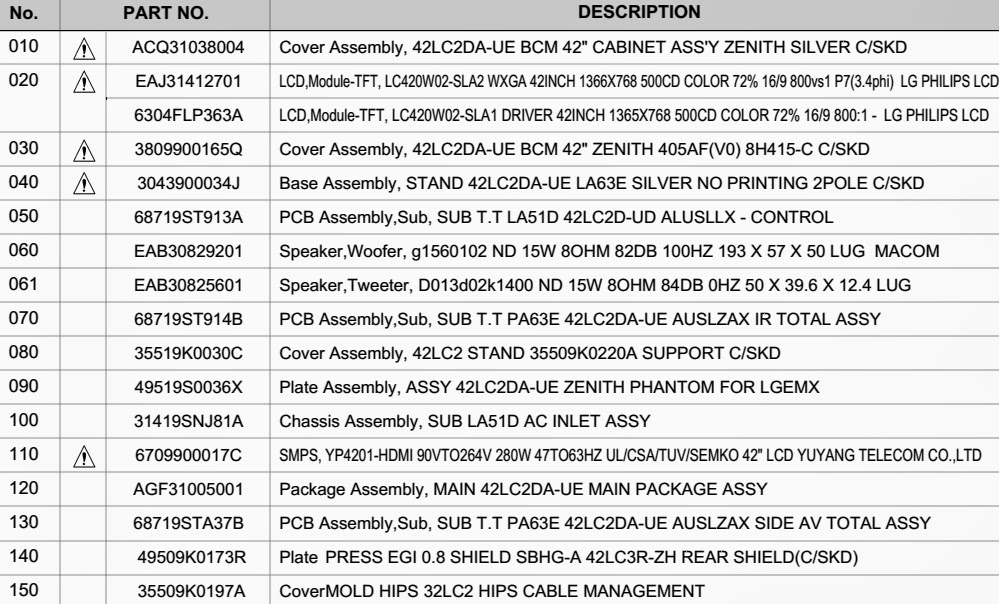
LCD TV_ZENITH _32LC2DA / 37LC2DA / 42LC2DA_EXPLODED VIEW & PARTS LIST

LCD TV_ZENITH _32LC2DA / 37LC2DA / 42LC2DA_EXPLODED VIEW & PARTS LIST


CLICK ON PICTURES TO ZOOM
32LC2DA
PARTS LIST
37LC2DA

42LC2DA

ZENITH - XBS444 - DVD+HI-FI VCR SYSTEM _ LANGUAGE CODES & COUNTRY CODES

ZENITH - XBS444 - DVD+Hi-Fi VCR System _ LANGUAGE CODES & COUNTRY CODES


LANGUAGE CODES
CLICK ON THE TABLES TO ZOOM IN
COUNTRY CODES
Disc Language [Select a language for the disc’s Menu, Audio, and Subtitle.]
  • Original: The original language set for the disc is selected.
  • Other: To select another language, use the number keypad to enter the corresponding 4-digit number according to the language code list.

Thursday, 14 March 2019

ZENITH DVR-313 - POWER SUPPLY [SMPS] - SCHEMATIC (CIRCUIT DIAGRAM) - DVD RECORDER

ZENITH DVR-313 - POWER SUPPLY [SMPS] - Schematic (Circuit Diagram) - DVD RECORDER


SMPS SCHEMATIC

CLICK ON THE SCHEMATIC TO MAGNIFY

Wednesday, 13 March 2019

ZENITH MBR3447 UNIVERSALS REMOTE PROGRAMMING AND CODE LIST

ZENITH MBR3447 UNIVERSALS REMOTE PROGRAMMING AND CODE LIST


PROGRAMMING AND CODE LIST


PROGRAMMING THE REMOTE

1.Turn on the device you’re programming for the remote control .
2.Press and hold the PRG key until the indicator light turns on .
3.Press the key for the device you ’r e trying to program ( CABLE , V C R , AUX , T V) .
4.Enter the cod e 0-0-0 (zero-zero-zero) , then press the ENTER key right away.
5.Aim the remote at the correct device and press
6.POWER . Allow a second to pas , then push the POWER key again . Repeat until the device turns off .
(This is a trial and error process , so it may be necessary to repeat these steps until the remote finds your code .)
7.Push ENTER to save the code .
8.Press PO WER to turn the device back on

CODE LIST FOR TELEVISION

Admiral . . . . . . . 1 1 6 1 21 130 133
Adventura T V/ V CR 154
Akai . . . . . . . . . . 104
Amark . . . . . . . . 103 146
AOC . . . . . . . . . . 104
Bell & Howell . . . 121
Broksoni c . . . . . . 131 136
Candle . . . . . . . . 139
Centurion . . . . . . 11 9
Citizen . . . . . . . . 121 139
Contec . . . . . . . . 141
Coronado . . . . . . 103
Crown . . . . . . . . 103
CurtisMathes . . . . 11 6 1 1 9 121
Daewoo . . . . . . . 149 1 59
Daewoo T V/ V CR . . 148
Daytron . . . . . . . 119
Elektra . . . . . . . . 121
Emerson . . . . . . . 103 1 04 123 124 131 136 145
Emerson T V/ V CR . . 158
Fisher . . . . . . . . . 109 11 8
Funai T V/ V CR . . . . 154
General Electric . . 106 107 11 4 11 6 11 7 161
Goldstar . . . . . . . 103 104 11 9 147
Goldstar T V/ V CR . . 153
Hitachi . . . . . . . . 102 103 129 1 63
J. C. Penney . . . . . 104 110 114 117 119
J V C . . . . . . . . . . 125 132 164
K MC . . . . . . . . . . 103
KT V . . . . . . . . . . 103 104 138
Kurazai . . . . . . . . 121
Lodgenet . . . . . . . 121
Logik . . . . . . . . . 121
LXI . . . . . . . . . . 133 137
Magnavox . . . . . . 103 11 2 11 3 117 119 127
128 139 165
Magnavox T V/ VCR 173
Majestic . . . . . . . 121
Marantz . . . . . . . 104 120 155
Megatron . . . . . . . 146
Memorex . . . . . . . 12
M GA/Mitsubishi . . . 104 11 9 120 130 140 155
Montgomery Ward 103 104 105 113 114 119
121 130 133
NEC . . . . . . . . . . 104 119
Panasonic . . . . . . 106 107 160 1 66
Panasonic T V/ VCR 174
Philco . . . . . . . . . 103 104 112 113 139
Philips . . . . . . . . 112 113
Pioneer . . . . . . . . 135
Portland . . . . . . . 103
ProScan . . . . . . . 116 157 162 167
Quasar . . . . . . . . 106 107
RCA . . . . . . . . . . 104 116 126 157 161 162 167 168
Realistic . . . . . . . 105 123  24
Sampo . . . . . . . . 119
Samsung . . . . . . . 103 119 134 1 41
Sanyo . . . . . . . . . 108 109 118
Scott . . . . . . . . . 119 124
Sears . . . . . . . . . 103 108 109 110 111 118 134
Sharp . . . . . . . . . 103 105 122 133 137 156 169
Signature 2000 . . . 103 104 105 113 114 119
121 130 133
Sony . . . . . . . . . 115 143 151 170
Soundesign . . . . . 139
Sylvania . . . . . . . 112 113 117 119 127 128 139
Symphonic T V/ VCR 154
Tatung . . . . . . . . 106
Tekni ka . . . . . . . . 103 112 121 1 24 1 39
Telerent . . . . . . . 103 121
Toshiba . . . . . . . 110 111 134 1 71
XR 1 000 . . . . . . . 121
Yorx . . . . . . . . . . 119
Zenith . . . . . . . . 101 149 175
Zenith T V/ VCR . . . 153 154 172

Wednesday, 6 March 2019

ZENITH ZN411 CODE LIST FOR TELEVISION AND HOW TO PROGRAM THE UNIVERSAL REMOTE - UNIVERSAL ZENITH 3 DIGIT CODE FOR TELEVISION

ZENITH ZN411 code list for television and how to program the universal remote - Universal Zenith 3 digit code for television


                                                Category: Universal remote programming and codes

Contests of this article 

  • Entering the code directly 
  • Code search
  • Codes for television 

ZENITH ZN411


Direct Code setup
1 Press and hold the Code Search button until the red indicator stays on Release the Code Search button.
2 Press and release the desired mode button (TV, VCR, etc) The red indicator blinks, then stays lit.
3 Enter the 3 digit code from the code tables Note: after a valid code entry, the red indicator turns off For an invalid code, the red indicator flashes.
4 With your device on, press CHANNEL Up If the device responds, no further programming is required Note: If some buttons do not operate your equipment, try one of the other codes for your brand.
Programming Using Code Search
1 Manually turn on the device (TV, VCR, etc) to be controlled.
2 Press and hold Code Search button until the red indicator stays on Release the Code Search button.
3 Press and release the desired mode button (TV, VCR, etc).
The red indicator blinks, then stays lit.
4 Press the Channel Up button repeatedly (up to 300 times) until the device to be controlled changes channel The red indicator blinks, then stays lit If you accidentally overshoot the code required, press the Channel Down button to backtrack through the library until the device changes channel Pressing Channel Up changes direction to forward again Press and release the Mute button to install the code.
The above assumes that you want to store VCR codes under the VCR button, DVD codes under DVD, etc If you want to store a VCR code under DVD, etc, first follow the procedure on page 10 and try ANY DVD code from the code tables, eg press DVD in step 2, page 10, and then enter ANY VCR code Then follow the steps above.
Note: If the device does not have a Channel Up button, use Play (VCR only) or Power instead Code Search starts from the currently stored three digit number under that mode eg if the mode has 100 codes and the currently stored code is 050 then the Code Search starts from 051 continuing to 100 before looping back to 000 and finishing at 050 This simplifies the process if you find that several preprogrammed codes operate your device by allowing you to bypass codes already tried.
Identifying the code 
1 Press and hold Code Search button until the red indicator stays on Release the Code Search button.
2 Press and release the desired mode button (TV, VCR, etc)
The red indicator blinks, then stays lit.
3 Press and release the Code Search button The indicator light blinks off.
4 To find the first digit for the code stored under the mode key pressed in step 2, press each numeric key from 0-9 in turn When the indicator light blinks off the number you pressed is the first digit for the code you are searching for 5 To find the second digit, repeat step 4, this time when the indicator light blinks off this is the second digit.
6 Repeat step 4 again to find the third digit.
UNIVERSAL ZENITH 3 DIGIT CODE FOR TELEVISION 
A
ABEX  120
ADMIRAL   701 918
ADVENTURA   019
AIKO  407
AIWA  121 221
ALLERON  206
AMARK  603
AMTRON  906
AKAI  801
AMSTRAD 520
ANAM NATIONAL 104 805  901 906 920
AOC  002 003 102 119 217 302 502 814
ARCHER 603
AUDIOVOX  906
B
BANG & OLUFSEN 620
BELCOR 002
BELL & HOWELL 506 601 701
BRADFORD   906
BROKSONIC 215 316
BROKWOOD 002
C
CANDLE  002 019 402 502
CAPEHART 119
CELEBRITY 801
CENTURION 502
CETRONIC  805
CITIZEN  002 112 402 407 502 512 701 805 906 319
CLAIRTONE 003
CLASSIC  805
CLP 018
CLP CLASSIC  007 006 002
COLORTYME 002 502 602
CONCERTO 002 502
CONCIERGE 713
CONTEC/CONY 003 802 805 902 906
CRAIG 805 906
CROWN 805 906
CURTIS MATHES 002 103 112 502 506 512 601 701 704
CXC 805 906
D
DAEWOO 002 102 110 214 303 311 314 403 407 415 502 503 611 614 805 809 909
DAYTRON 002 502
DIMENSIA 601 704
DUMONT 002 713
DYNASTY 805
E
ELEKTRA 701
ELECTROBAND 003 801
ELECTROHOME 002 502 803 901 914
EMERSON  002 003 004 005 104 105 106 115 204 205 206 213 304 305 316 319 405 502 505 506 519 604 605 705 804 805 903  904 905 906
ENVISION 002 502
F
FISHER 506 522 606 619 902
FUJITSU 206 321
FUNAI  206 805 906
FUTURETEC 805 906
G
GE  002 006 007 018 107 114 310 312 502 601 704 719 803 806 810 901 911
GIBRALTER 002 713
GOLDSTAR 002 102 117 207 217 307 502 818 914
GRUNDY 206 906
H
HALLMARK 002 502
HARVARD  906
HITACHI  002 016 116 216 315 410 502 507 515 519 607 615 622 701 707 710 715 815 902 915
I
IMA  906
INFINITY 807
INTEQ  713
J
JANEIL  019
JBL  807
JCB  801
JC PENNY  002 007 102 107 112 310 312 402 502 512 601 704 719 803 806 818 907
JENSEN 002 502
JVC  007 107 108  308 510 607 902
K
KAWASHO  002 502 801
KAYPANI 119
KEC 805
KENWOOD 002 502 914
KLOSS NOVABEAM  019 408 508
KONKA 203 208 219 306 317 417
KTV 003 213 319 608 703 805 906
L
LODGENET 601 701
LOEWE 722 807
LOGIK 601 701
LUXMAN 002 502
LXI 002 312 502 506 512 601 704 719 807
M
MAGNAVOX 002 009 109 118 209 309 402 408 502 508 510 807 914 917MAJESTIC 601 701
MARANTZ  002 502 807
MEGATRON  002 502 507
MEI  003
MEMOREX  002 115 206 502 506 601 701 706
MGA 002 102 206 502 619 803 914
MIDLAND 007 107 312 713 719 818
MINUTZ 806
MITSUBISHI 002 102 206 502 510 619 709 803 814 914
MONTGOMERY WARD 601 701
MOTOROLA 901 918
MTC 002 003 102  112 502 512
MULTITECH  906
MULTIVISION 010
N
NAD  002 120 502 512
NEC  002 102 110 111 502 510 602 901
NIKEI  805
NIKKO  002 407 502
NTC  407
O
ONKING  805
ONWA  805 906
OPTIMUS 120 618
OPTONICA 111 918
ORION  105 115 713
P
PANASONIC  007 107 416 516 608 618 718 807 901
PHILCO  002 009 102 109 309 402 408 502 508 807 901 914
PHILIPS  002 009 020 109 122 202 209 210 222 310 322 402 408 422 508 510 807 822 901 914 917 919 922
PHILIPS/MAGNAVOX  020 422 919 922
PILOT  002
PIONEER 002 120 502 519 610
PORTLAND 002 102 407 502
PRECISION  218
PRICE CLUB  112
PRISM  107
PROSCAN  312 601 704 719
PROTON  002 119 220 502 820 910
PULSAR  713
PULSER 002
Q
QUASAR  007 107 416 516 608 618 718 807 901
R
RADIO SHACK/REALISTIC  002 021 111 117 406 502 506 601 618 704 705 805 818 906 914
RCA  002 021 011 102 211 302 312 318 320 406 409 411 420 502 511 514 519 601702 711 719 809 811 901 909 911 912 914
RHAPSODY  003
RUNCO  713
S
SAMPO  002 119 502 818
SAMSUNG  002 012 102 103 112 212 502 512 818 914
SAMSUX  502
SANSUI  115 215
SANYO  002 412 506 522 612 619 902
SCOTCH 002 502
SCOTT  002 004 105 206 502 805 906
SEARS  002 112 206 312 502 506 512 520 601 612 619 704 719 902 914
SHARP 002 013 014 111 502 509 712 812 813 913 918
SHOGUN  002
SIGNATURE  601 701 903
SIMPSON  402
SONIC  003
SONY  202 414 708 801
SOUNDESIGN  002 206 402 502 805 906
SPECTRAVISION  921
SQUAREVIEW  520
SSS  002 805 906
STARLITE  906
SUPREMACY  019
SUPREME  801
SYLVANIA  002 009 109 209 309 402 408 502 508 717 807 914 917
SYMPHONIC  520 904 906
T
TANDY  918
TATUNG  901
TECHNICS 007 107
TECHWOOD 002 007 107 502
TEKNIKA  002 019 102 112 206 209 402 407 502 512 601 618 701 805 902 906
TELECAPTION  313
TELERENT  601 701
TERA 002 220
TMK  002 502
TOSHIBA  112 313 413 419 506 510 512 517 613 902
U
UNIVERSAL 310 806
V
VICTOR 607
VIDTECH 002 102 502
VIKING  019
W
WARDS  002 004 009 102 109 111 206 209 310 408 502 508 513 601 701 704 806 807 914
WHITE WESTINGHOUSE 311 611
Y
YAMAHA 002 102 502 914
Z
ZENITH  002 008 115 215 405 407 507 601 701 713 903 916

Monday, 4 March 2019

HOW TO ENTER SERVICE MODE - ADJUSTMENTS - ZENITH C27A25 – C36A26

How to enter Service Mode - Adjustments - Zenith C27A25 – C36A26

Zenith C27A25, C27A25T6, C32A26, C32A26T6, C36A26, C36A26-8, C36A26T6, C36A26T6-8
FACTORY MENU (Service Mode menu) ADJUSTMENTS
To access the Factory Menu, press and hold the MENU key until the User Menu display disappears, then press 9876, and then ENTER.
The black bar near the top of the screen indicates the part number of the software in the TV set. To the lower right is a number indicating that the module has been tested. The date on the black bar near the bottom left of the screen indicates the date the module went through the factory.
When the Factory Menu appears, it displays the fourth Factory Menu item: VERT POS. Use the SELECT UP/DOWN keys to toggle through all of the adjustments. Uses ADJUST to make a change to the selected item.

00 FACT MENU: Use SELECT UP and DOWN Keys to select item 00, the Factory Mode. The Factory uses this item when the module is being tested. It has two positions: 0 and 1. In the field, this item should always be left off (Zero is off).
When this item is off, only the first seven items in the Factory Menu can be accessed. They appear one at a time near the middle left of the screen. When this item is set to 1, 59 menu items are available.  In the Factory Menu, only the selected menu item is displayed, near the top of the screen, as shown in the figure.
When the Factory Menu is on, the AC Power-On feature is always enabled regardless of the setting of AC ON in the Factory Menu. The TV set will automatically come on when AC is applied.  Use the remote to reenter the Factory Menu to turn the Factory Menu off. Setting the clock or running the Auto Program feature in the customer Set Up menu can also turn off the Factory Mode.
01 PRESET PX: Stores customer menu adjustments in the nonvolatile memory of the EAROM. Selections are Custom and Preset-Store. Settings for Contrast, Brightness, Color and Tint are stored in this manner. 0 is custom and 1 is Preset stored.
02 VERT P0S: Moves On-Screen Displays vertically. The Range is from 0-30. This adjustment is generally set at 15.
03 H0RZ POS: Moves On-Screen Displays horizontally.  Range is from 1-45. Generally set at 20.
04 FEATURE LEVEL: There are three positions: 0,1 and 2.The three positions are used at the factory to program the module for the correct features. In order to change the level, short pins 3 and 4 togather on connector 4G9 on the main module.
NOTE: BE CAREFUL! IF THE WRONG PINS ARE SHORTED, THE MODULE CAN BE DAMAGED.  BE SURE TO REMOVE THE JUMPER AFTER THE LEVEL HAS BEEN SET.
Level 0 is used for private label sets.  Levels 1 and 2 are used for Zenith sets.
05 BAND: There are eight positions.
0 is Broadcast fixed 4 is Broadcast afc.
1 is CATV afc 5 is CATV fixed
2 is HRC afc 6 is HRC fixed
3 is ICC afc 7 is ICC fixed
06 POWER ONLY: There are two positions, 0 is off and 1 is AC on. In position 1 the unit will turn on and off when AC power is applied and removed.
07 RF SUB BRT: (RF brightness) Sets adjustment range of customer control for brightness in RF mode. Range is 0-63. A typical value is 32.
08 AUX SUB BRT: (Auxiliary Brightness) Sets adjustment range of the customer control for brightness in AUX mode. Range is 0-63. Typical value is 32.
09 MAX CONTRAST: Sets adjustment range of customer control for contrast. Range is 0-63. Typical value is 63.
10 VERT SIZE: (Vertical Size) Range is 0-254.
11 HORZ SIZE: (Horizontal Size) Range is 0-254.
12 VERT PHASE: (Vertical Phase) Shifts picture vertically.  Range is 0-7.
13 HORZ PHASE: (Horizontal Phase) Shifts picture horizontally. Range is from 0-30.
14 HORZ AFC: Fast/slow response. Horizontal frequency control. Range is 0-1.
15 BAND PASS: Sets use of ICX2200’s internal band pass chrome filter. Range is 0-1. Set to 1.
16 TRAP 3.58: Zero is off, one is on. Set to 1 for normal TV operation. Set to 0 if Y/C is used or chassis has a comb filter.
17 RED CUT: B&W tracking adjustment. Range is 0 to 254. Typical value is 0.
18 GREEN CUT: B&W tracking adjustment. Range is 0- 254. Typical value is 0.
19 BLUE CUT: B&W tracking adjustment. Range is 0-254. Typical value is 0.
20 GREEN GAIN: B&W tracking adjustment. Range is 0- 255. Typical value is 144.
21 BLUE GAIN: B&W tracking adjustment. Range is 0-254. Typical value is 144.
22 60HZ SW: (60 Hertz Switched) The range is 0 to 2. Set to 2.
23 WHITE COMPRESS: (White Compression) The range is 0 to 1. Set to 1. 0 = Enable and 1 = Disable.
24 6 KEY SYSTEM: Keyboard type. Set to 1 for 6 key and 0 for 10 key.
25 FRONT JACK: 1 = enabled, 0 = disabled
26 XTAL SELECT: Select the xtal oscillator for OSD. Range is 0-1
27 SOUND ATT: Composite audio level adjustment. Range is 0 -63.
28 SOUND ATT2: Composite audio level adjustment for tuner 2. Range is 0 -63.
29 RF AGC: (Rf Automatic Gain Control) Range is from 0-63. 48 is a general setting. Tune in weakest available channel and adjust for a snow- free picture.
30 PIF VCO: Range is 0-127. 70 are typical.
31 AUDIO ATT: Audio Attenuator for main tuner. Range is 0-15. 9 is typical.
32 AUDIO VCO: Audio voltage controlled oscillator. Range is 0 -63. 31 is typical.
33 AUDIO FILTER: (Second Audio Program Voltage-Controlled Oscillator) Stereo, SAP, and dBx filter adjustment. Range is from 0-63.
34 AUDIO SPECTRL: Adjustment of stereo separation (3kHz). Range is 0-63.
35 WIDE BAND: Adjustment of stereo separation (300kHz). Range is 0-63.
36 DELAY PIP SELECT: Delay of output signal. Range is 0 -15. Typical is 15.
37 PIP V LEV: PIP auto gain control. Range is 0 - 15 . Typical is 14.
38 YOFSET: PIP luminance offset. Range is 0 - 3. Typical is 0.
39 PIP PLLITC: PIP PLL synchronization. Range is 0 - 3. Typical is 0.
40 PIP HFP: PIP horizontal fine position. Range is 0 - 31. Typical is 0.
41 PIP INCRA: PIP Regenerated Color Carrier Frequency. Range is 0 - 31. Typical is 15.
42 PIP RED CUTOFF: Adjustment of blanking level. Range  is 0 - 15. Typical is 0.
43 PIP GREEN CUTOFF: Adjustment of blanking level. Range is 0 - 15. Typical is 0.
44 PIP BLUE CUTOFF: Adjustment of blanking level. Range is 0 - 15. Typical is 0.
45 PIP COLOR FRAME: Range is 0 - 63. Typical is 16.
46 PIP FR WID H: PIP Horizontal width of frame. Range is 0 - 7. Typical is 1.
47 PIP FR WID V: PIP Vertical size of frame. Range is 0 - 3. Typical is 0.
48 PIP C KILL: PIP Color Killer threshold. Range is 0 - 3. Typical is 2.
49 PIP Y PEAK: PIP Luminance peaking. Range is 0 - 7. Typical is 4.
50 PIP R GAIN: PIP Red Amplitude. Range is 0 - 254. Typical is 190.
51 PIP G GAIN: PIP Green Amplitude. Range is 0 - 254. Typical is 190.
52 PIP B GAIN: PIP Blue Amplitude. Range is 0 - 254. Typical is 190.
53 PIP COLOR ON: PIP Color on/off. Range is 0 - 1. Typical is 0.
54 PIP FRAME SEL: 3D PIP Frame Selection. Range is 0 - 1. Typical is 1.
55 PIP X1 POSITION: Range is 0 - 127.
56 PIP Y1 POSITION: Range is 0 - 254.
57 PIP X2 POSITION: Range is 0 - 127.
58 PIP Y2 POSITION: Range is 0 - 254.
SMPS SCHEMATIC
HORIZONTAL & VERTICAL SCAN OUT
Click on the pictures to Magnify