ACCELL FITNESS BREMSHEY-SPORT_ORBIT ELLIPTICAL TRAINER _ CALIBRATING THE SERVO MOTOR & FLYWHEEL BRAKE CABLE
It is important that the brake mechanism is set up so that it
is possible to achieve the correct minimum and maximum settings. When a new servo-motor
is fitted the following procedure should followed.
- Whilst rotating the rear drum, increase the resistance with the meter keys to maximum checking that the cable and flywheel slider is moving freely.
- Whilst rotating the rear drum, decrease the resistance with the meter keys to minimum checking that the cable and flywheel slider is moving freely.
- At minimum setting check that the braking resistance is minimal and that there is a 2mm gap between the bottom of the slider and its case.


With this system, data is sent from
the display meter to the brake control circuit board as a resistance level is
selected either via a key press or a program. The board in turn supplies power
to the electromagnetic brake coil to increase the magnetic field in order to
apply the resistance.
If
it is not possible to apply or control the resistance the fault is typically
found within the brake control circuit. However, failure within the wiring set
or the meter can also be a cause. It is quite rare for the electromagnetic coil
to fail. The resistance values for the
coil can be increased by adjusting the trimpot on the circuit board. However,
great care should be taken with small adjustments and testing in order to avoid
unstable resistance control. The
circuit board can be replaced by removing 4 x screws fixing it to the frame and
unplugging the cables. If required, the coil can be detached by removing the
bolts.
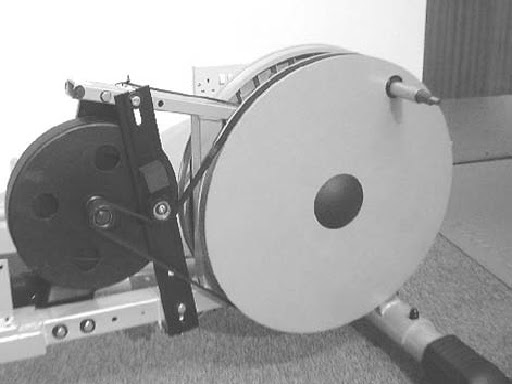
FLYWHEEL AND TRANSMISSION
The transmission system consists of a
rear drum which drives the resistance flywheel via a grooved belt which is
adjusted and controlled with a tensioning wheel device. This system has varied
between models and the 2 main different systems are shown.


TRANSMISSION BELT
The transmission belt if not
correctly aligned tensioned can cause noise and long-term damage to the belt
and other associated components. It will be necessary to remove both covers and
disconnect both foot –tubes to work on transmission problems. If the drive belt has removed itself or is
worn/damaged after replacing the belt it will be necessary to check the tension
and alignment to establish the cause of the failure.
REPLACING DRIVE BELT [FOR TYPE-1]
- Slacken off the vertical tensioning bar by loosening the upper and lower locking bolts (f) and then remove lower adjusting bolt (g)
- Remove the belt rotating by the drum clockwise whist feeding the belt off the flywheel boss. (See diagram 16 below) (Warning! Be careful not to trap fingers at this point.)
- Before replacing the belt ensure that the grooves of the rear drum and resistance flywheel boss are cleared off any dirt or debris.
- Recommend that at this point the lower adjuster bolt is unscrewed, the spring that is sometimes located at the bottom of the vertical tensioning bar is removed, and the adjusting bolt re-fitted but not tightened. The spring can be discarded as it is not absolutely required.
- Set the rear drum so that the axle stub is in a vertical position. Introduce the belt by fitting it over the resistance flywheel boss (groove side down) and under the upper tension wheel.
- Run the belt on to the rear drum by feeding it round the top of the drum whilst rotating the drum in a clockwise direction. Continue to rotate the drum whilst forcing the belt to remain in place with your hand. Please ensure that at this point the belt remains on the resistance flywheel boss by observing its position during rotation. (Warning! Be careful not to trap fingers at this point.)


- Adjust the drive belt tension. Screw the lower adjusting bolt until a satisfactory tension is achieved. The recommended tension should be set so that with firm pressure the drive belt can only be deflected in one direction by approximately 3 mm at the point shown. Inadequate tension can cause the belt to slip producing a squealing noise and unsmooth action Too greater tension will place undue pressure on the rear drum and bearings. When set re-tighten upper and lower locking bolts.

CHECKING THE SETTING BELT ALIGNMENT
- Rotate drum in an anti – clockwise direction (simulating forward motion in use). Observe the belt alignment. Rotate the drum in the opposite direction (simulating reverse motion in use). Observe the belt alignment. If the belt runs out of line it may be caused by incorrect tolerance of frame components.
- Dressing the belt. We recommend that at this point that both sides of the belt are ‘dressed’ with light coating of French chalk as this can reduce noise and increase longevity of the belt
TYPE -2
- Slacken off the vertical tensioning bar by loosening the upper and lower locking bolts (h) and then remove lower adjusting bolt. Unhook the spring attached to the floating tension wheel and let the wheel and arm fall away.
- Remove the belt rotating by the drum clockwise whist feeding the belt off the flywheel boss. Se diagram 16 above) (Warning! Be careful not to trap fingers at this point.)
- Before replacing the belt ensure that the grooves of the rear drum and resistance flywheel boss are cleared of any dirt or debris.
- Recommend that at this point the lower adjuster bolt (i) is unscrewed, the spring that is sometimes located at the bottom of the vertical tensioning bar is removed, and the adjusting bolt re-fitted but not tightened. The spring can be discarded as it is not absolutely required. If you wish to remove the vertical tensioning bar then unscrew and remove the upper and lower locking bolts completely and the bar can be removed.
- Set the rear drum so that the axle stub is in a vertical position. Introduce the belt by fitting it over the resistance flywheel boss (groove side down) and under the upper tension wheel (k), under over the top of the floating tension wheel.
- Run the belt on to the rear drum by feeding it round the top of the drum whilst rotating the drum in a clockwise direction. Continue to rotate the drum whilst forcing the belt to remain in place with your hand. Ensure that at this point the the belt remains on the resistance flywheel boss by observing its position during rotation. (Warning! Be careful not to trap fingers at this point.)
ADJUST THE DRIVE BELT TENSION
- Screw the lower adjusting bolt until a satisfactory tension is achieved. The recommended tension should be set so that with firm pressure the drive belt can only be deflected in one direction by approximately 3 mm at the point shown. Inadequate tension can cause the belt to slip producing a squealing noise and unsmooth action Too greater tension will place undue pressure on the rear drum and bearings. When set re-tighten upper and lower locking bolts.
CHECKING AND SETTING BELT ALIGNMENT
- Rotate drum in an anti – clockwise direction (simulating forward motion in use). Observe the belt alignment. Rotate the drum in the opposite direction (simulating reverse motion in use). Observe the belt alignment. If the belt runs out of line it may be caused by incorrect tolerance of frame components. Now reattach the floating tension arm spring so that the wheel is now applying pressure to the drive belt. Rotate the drum as indicated previously. If the belt moves out of alignment the floating arm assembly may need to be adjusted by bending the floating wheel arm in or out. If the belt is running out (towards the covers) bend the arm towards the frame. If the belt is running in (towards the frame) bend the arm towards the covers. Only a small amount of movement may be necessary to realign the belt. This operation can be assisted if the floating wheel assembly is removed from the machine by unscrewing the securing nut.
DRESSING THE BELT
- Recommend that at this point that both sides of the belt are ‘dressed’ with light coating of French chalk as this can reduce noise and increase longevity of the belt.