BREMSHEY-SPORT_ORBIT ELLIPTICAL TRAINER_SERVICE HELP

OPENING UP COVER FOR REPAIR & ADJUSTMENT
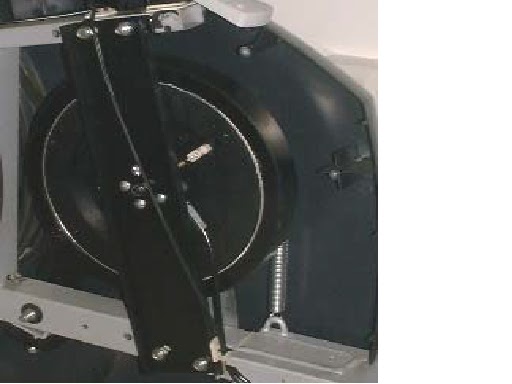
To access the internal components of the Orbit it is necessary to remove one or both sides of the main cover sets. In order to do this it will be necessary to disconnect the foot tube from the rear drum axle. In general, access to the transmission is gained by removing left covers and brake system requires right-hand.
MODELS WITH FOOT TUBE HEIGHT ADJUSTMENT
- Unscrew adjuster and allow tube to move to lower position.
- Remove cap from rear axle (if applicable). Remove locking nut, washer and spacer. Withdraw foot tube assembly away from drum. If necessary rotate the drum until the tube eases off.
MODELS WITH OUT FOOT HEIGHT ADJUSTER
- Remove cap from rear axle (if applicable). Remove locking nut, washer and spacer. Withdraw complete foot tube and swing arm assembly away from drum. If necessary rotate the drum until the tube eases away.


- The covers can now be removed. Depending on the model concerned there may be more than one cover to remove. There are several screws located on the perimeter of the covers. Some of these locate into the frame and some into the lugs within the cover itself. (be aware of the screw positions and types. Note: Before removing the covers from a machine powered by mains transformer it will be necessary to remove the power socket from the rear of the cover. To do this, remove all screws. Reach inside the cover and grip the power socket whilst removing the thin nut from the outside of the socket and carefully withdraw the socket and cable assembly. Reverse procedure when work complete.
SPEED SENSOR AND RESISTANCE MECHANISMS
- A reed/proximity switch mounted next to the left rear drum measures the speed of rotation. One or two small magnets are mounted in the rear drum and at each pass the switch opens and closes sending a ‘pulse’ to the meter either directly or via the control circuit board in the case of electro magnetically braked units.

RESISTANCE MECHANISM
There are 3 types of brake control
used. The first 2 consist of a flywheel unit with an expanding and contracting
central magnetic unit activated by a cable. These are controlled mechanically
by the rotation of a control knob or electro-mechanically by use of a servo-motor.
The third type is electromagnetic which employs an external coil which when
powered slows the rotation of the flywheel.
MANUAL RESISTANCE CONTROL
There 3 basic components to this
type.
Brake control knob
Brake flywheel mechanism
Cable connection (This may be located
at the top of the tube or at the lower end depending on the model).


PROBLEM: Resistance can be achieved but max
and min settings incorrect.
CHECK: Brake cable requires adjusting at the
flywheel brake end, or:
Brake
cable requires adjusting at connection between upper and lower cable.
Resistance doesn’t change or is not smooth:
Check cable is moving freely at all
points. Adjust cable or change parts as
necessary.
The
cable adjuster can be used to set the correct positions for maximum and minimum
resistance. The securing nut should be released
and the adjusting nut turned to increase or decrease the tension of the cable.
Observe the position of the brake slider. When it is moved towards the center
of the flywheel the resistance is at its least and further away the resistance
is at its greatest.
SERVO MOTOR RESISTANCE CONTROL
The servo-motor is located next to the flywheel unit. When a
resistance level is selected via the display meter, either by manual key
presses or via a program change, power is supplied to the motor causing it to
rotate, pulling the brake cable in or out depending on the rotational
direction. In order for the servo-motor
to operate the electronics must receive pulses from the flywheel speed sensor
(See section on speed sensor). There is
a slight delay between receiving the first pulse and the servo-motor operating.
Therefore, in order to test the servo-motor brake mechanism the sensor must
receive constant pulses by rotating the rear drum.
OPERATION
In order to test the servo-motor unit it is necessary to
simulate the product in use. In models with a ‘Manual’ program (Control, Plus & Discovery) this can be achieved by
rotating the rear drum by hand. Note: It can be made easier by removing the
drive belt from the rear drum.
REPLACING SERVO MOTOR UNIT
First remove the servo-motor brake cable (a) from the
flywheel brake mechanism. To achieve this, the tension must be released from the
cable. In order to do this the securing nut (b) should be released and the
adjusting nut turned to decrease the tension of the cable. Push the flywheel slider (c) down with a
screwdriver and the release the outer cable sleeve (d) from the servo-motor
securing point. Now lift the cable over
the motor capstan (e) and then slide out the cable end from the capstan slot. Detach the electronic cables from the
servo-motor to the wiring set. Undo the 4 screws (e) that mount the servo-motor
to the frame and remove the motor unit.
Refit new servo-motor by reversing the above procedure.
Taking care to refit the cable around the motor capstan in the correct direction
and avoiding strain on the cable which may damage the motor gearing mechanism.
It will then be necessary to calibrate the new motor.


