Motus USA Elliptical Cross Trainers M770E - M770EL – How to adjust Belt – How remove the rear cover – How to replace the belt
Motus
USA Elliptical Cross Trainers M770E - M770EL: How to Replace the REAR COVER
1)
The following tools are required.
Philips Screw Driver, Wrench Sets, Snap Ring Pliers
2) Remove two BUTTON CROSS BOLT securing left REAR COVER-L (133) to right REAR COVER-R
3) Remove two BUTTON CROSS BOLT and two ALLEN BOLT securing left REAR COVER-L to the Frame, and then remove left REAR COVER-L.
4) Remove two BUTTON CROSS BOLT and two ALLEN BOLT securing right REAR COVER-R to the Frame, and then remove right REAR COVER-R
5) Remove six BUTTON CROSS BOLT and then lift REAR COVER-C up.
6) Replace the specific part
7) Install the REAR COVER-C, REAR COVER-R and REAR COVER-L in reverse order.
How
to Adjust the Drive Belt (or Pulley Belt) Tension
1)
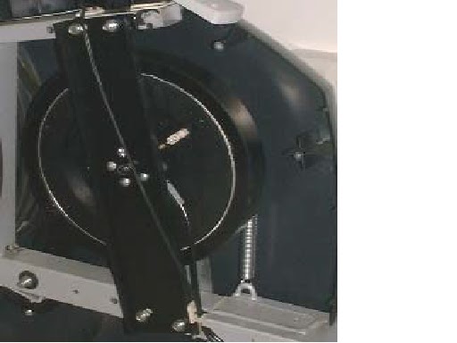
Loosen two HEX LOCK NUTs a little using
17mm spanner.
2) To increase the tension, turn HEX NUT clockwise with a 19mm spanner while holding H/S HEX BOLT with another 19mm spanner. Initial tension is set to 190 Hz. To decrease the tension, turn HEX NUT counterclockwise.
3) Make sure that PULLEY BELT does not slip and then install the REAR COVER-C, REAR COVER-R and REAR COVER-L in reverse order.
How
to Replace the Drive Belt (or Pulley Belt)
1)
Loosen two HEX LOCK NUTs a little using
17mm spanner.
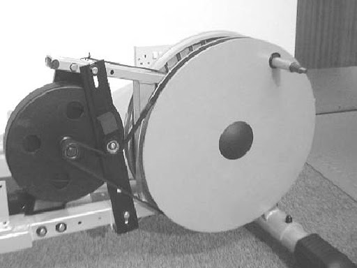
2) To loosen the PULLEY BELT , turn HEX NUT (21) counterclockwise with a 19mm spanner while holding H/S HEX BOLT with another 19mm spanner.
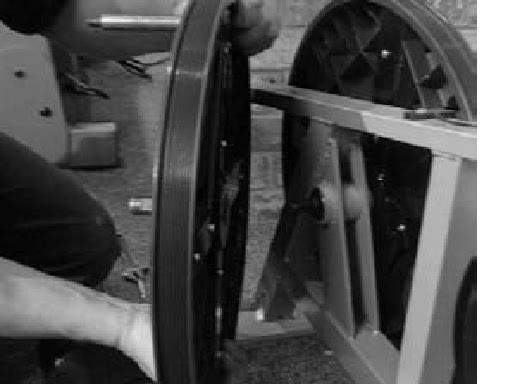
3) Derail the slackened PULLEY BELT from the PULLEY.
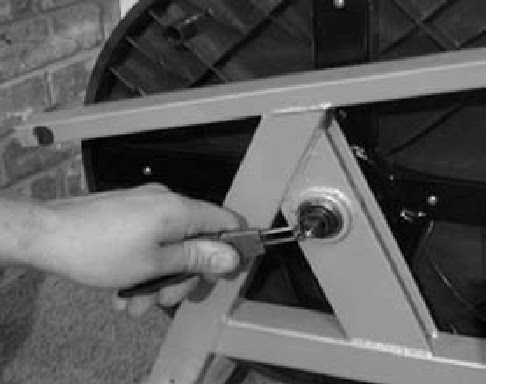
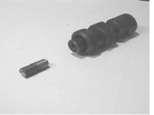
4) Remove CAP HEX NUT and PLANE WASHER using 24 mm spanner.
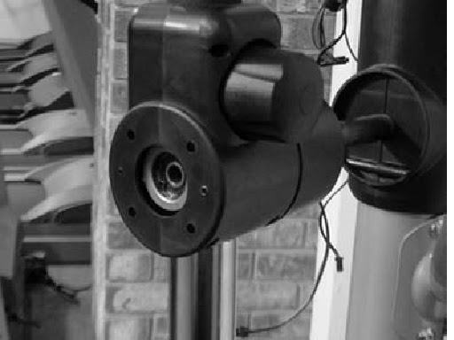
5) Pull COUPLER FRAME out of CRANK ASS’Y-230 by lifting it off.
6) Remove H/S HEX BOLT and HEX LOCK NUT using 21 mm Spanner and then slide CRANK ASS’Y-230 off the Shaft of the Pulley
7) Remove SQUARE KEY from the Shaft.
8) Remove four H/S HEX BOLTs using 17 mm spanner and then slide the BEARINGUCF206 off the Frame and Shaft of the Pulley.
9) To remove the CRANK ASS’Y-230 and BEARING-UCF206 in opposite side, repeat the same procedures as (4) thru 8).
10) Remove the PULLEY combined with the Shaft by taking it out toward the front of the Machine.
11) Remove the PULLEY BELT.
12) Install the new PULLETY BELT in reverse order.
13) If needed, adjust the Pulley Belt Tension.”
2) To loosen the PULLEY BELT , turn HEX NUT (21) counterclockwise with a 19mm spanner while holding H/S HEX BOLT with another 19mm spanner.
3) Derail the slackened PULLEY BELT from the PULLEY.
4) Remove CAP HEX NUT and PLANE WASHER using 24 mm spanner.
5) Pull COUPLER FRAME out of CRANK ASS’Y-230 by lifting it off.
6) Remove H/S HEX BOLT and HEX LOCK NUT using 21 mm Spanner and then slide CRANK ASS’Y-230 off the Shaft of the Pulley
7) Remove SQUARE KEY from the Shaft.
8) Remove four H/S HEX BOLTs using 17 mm spanner and then slide the BEARINGUCF206 off the Frame and Shaft of the Pulley.
9) To remove the CRANK ASS’Y-230 and BEARING-UCF206 in opposite side, repeat the same procedures as (4) thru 8).
10) Remove the PULLEY combined with the Shaft by taking it out toward the front of the Machine.
11) Remove the PULLEY BELT.
12) Install the new PULLETY BELT in reverse order.
13) If needed, adjust the Pulley Belt Tension.”
How
to Replace the Generator
1)
Disconnect two cables from the GENERATOR.
2) Loosen two HEX LOCK NUTs a little using 17mm spanner.
3) To loosen the PULLEY BELT , turn HEX NUT counterclockwise with a 19mm spanner while holding H/S HEX BOLT with another 19mm spanner.
4) Derail the slackened PULLEY BELT from the PULLEY.
5) Remove ALLEN BOLT , HEX LOCK NUT and PLANE WASHER securing the GENERATOR to the GENERATOR FRAME by using 4mm wrench and 10 mm spanner.
6) Remove the GENERATOR from the GENERATOR FRAME
7) Install new the GENERATOR in reverse order.
8) If needed, adjust the Pulley Belt Tension.
How
to Replace the UNIT BEARING – UCF206
The
procedure to replace the Bearing is same on both right side and left side.
1) Loosen two HEX LOCK NUTs a little using 17mm spanner.
2) To loosen the PULLEY BELT , turn HEX NUT (21) counterclockwise with a 19mm spanner while holding H/S HEX BOLT with another 19mm spanner.
3) Derail the slackened PULLEY BELT from the PULLEY.
4) Remove CAP HEX NUT and PLANE WASHER using 24 mm spanner.
5) Pull COUPLER FRAME out of CRANK ASS’Y-230 by lifting it off.
6) Remove H/S HEX BOLT and HEX LOCK NUT using 21 mm spanner and then slide CRANK ASS’Y-230 off the Shaft of the Pulley.
7) Remove SQUARE KEY from the Shaft.
8) Remove four H/S HEX BOLTs using 17 mm spanner and then slide the BEARINGUCF206 off the SHAFT ASS’Y.
9) Install new BEARING-UCF206 in reverse order.
10) If needed, adjust the Pulley Belt Tension.
How
to Replace the CRANK ASSEMBLY
1)
Loosen two HEX LOCK NUTs a little using
17mm spanner.
2) To loosen the PULLEY BELT , turn HEX NUT counterclockwise with a 19mm spanner while holding H/S HEX BOLT with another 19mm spanner.
3) Derail the slackened PULLEY BELT from the PULLEY
4) Remove CAP HEX NUT and PLANE WASHER using 24 mm spanner.
5) Pull COUPLER FRAME out of CRANK ASS’Y-230 by lifting it off.
6) Remove H/S HEX BOLT and HEX LOCK NUT using 21 mm spanner and then slide CRANK ASS’Y-230 off the Shaft of the Pulley.
7) Install new CRANK ASS’Y-230 in reverse order.