BOSE LIFESTYLE V35 – T20 – Adjustment procedure – Tap command - Audio system repair and service

Category: Audio System Repair and Service
Contents of this article
- AV35 Adjustment Procedure
- AV20 Adjustment Procedure
- Tap command
BOSE LIFESTYLE V35 – T20
AV35 Adjustment Procedures
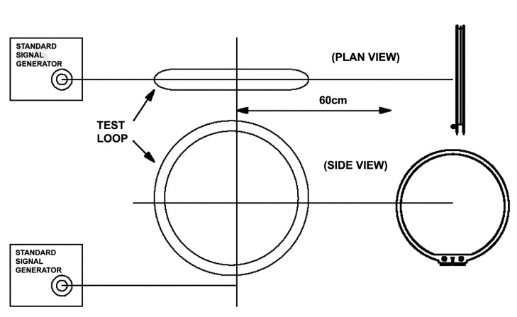
Refer to the figure below. The equivalent
field intensity is 26 dB less than the generator output level or 1/20th of the
output voltage. The signal levels given do not include this factor.
Measurements are taken from the record output.
Setup a computer to issue TAP commands.
1. AM Sensitivity Performance
Verification
1.1 Set the RF generator output for a 55 dBuV/m field intensity, 30% AM modulation, 1 KHz and the unit and RF generator to 1080 kHz.
1.2 The headphone output should measure < 10% THD+N.
2. AM Stop Level Adjustment, TAP
2.1 Set the RF generator to 1080 kHz, 30% AM modulation, 1 kHz modulation, 57 dBuV/m field intensity at the unit’s antenna.
2.2 Issue the TAP command TM set 2.
2.3 Set the generator to 1110 kHz , 61 dBuV/m field intensity.
2.4 Place the unit into seek and verify the unit stops at 1110 kHz.
2.5 Switch the RF generator for a 51 dBuV/m field intensity and verify the radio does not stop at 1110 kHz.
FM Tuner General Test Setup Connect the signal generator to the FM antenna jack J2001 using
a 50 to 75 Ohm matching network. Adjustments to the procedure’s stated signal
levels should be made to account for a signal level loss due to the matching
network and/or any other losses. Setup a computer to issue TAP commands.
3. FM Signal to Noise
3.1 Set the RF generator to 98.1 MHz, 1 kHz mono modulation, pilot off, 75 kHz deviation, 65 dBf at the unit’s FM antenna input.
3.2 Adjust the unit to 98.1 MHz.
3.3 Reference a dB meter to the left headphone output.
3.4 Turn off the modulation and pilot. The left headphone output should measure < -55dBr.
4. FM Sensitivity Verification
4.1 Set the RF generator to 98.1 MHz, 1 kHz mono modulation, pilot off, 75 kHz deviation, 20 dBf at the unit’s FM antenna input.
4.2 Measure the distortion at the left or right headphone output. It should be < 3.0% THD+N.
5. FM Stop Level Adjustment, TAP
5.1 Set the RF generator to 98.1 MHz (83.0 MHz for Japan), 1 kHz mono modulation, pilot off, 75 kHz deviation, 30 dBf, at the unit’s FM antenna input.
5.2 Issue the TAP command TM SET 3 (TM SET 4 for Japan).
5.3 Switch the RF generator to 98.7 MHz (83.3 MHz), 35 dBf at the units FM antenna input.
5.4 Place the unit into seek and verify that it stops at 98.7 MHz.
5.5 Reduce the RF generator to 25 dBf at the units FM antenna input.
5.6 Place the unit into seek. Verify the radio does not stop at 98.7 MHz.
6. FM Stereo Threshold Setting
6.1 Set the RF generator to 98.1 MHz (83.0 MHz for Japan), 1 kHz L= -R modulation, pilot 10%, 75 kHz deviation, 40 dBf, at the unit’s FM antenna input.
6.2 Issue the TAP command TM SET 5 (TM SET 6 for Japan).
6.3 Increase the RF generator to 45 dbf. Verify the radio is in stereo mode.
6.3 Decrease the RF generator to 35 dbf. Verify the radio is in mono mode.
7. Completion of Tuner Adjustments
Note: Any adjustments made, must be stored to the EEPROM.
7.1 Enter the TAP command “NV” (without the quotes)
AV20/35 Performance
Verification Procedures
6. Input/Output Tests
6.1 Connect the PS III bass module to the console’s acoustimass output.
6.2 Connect a TV to the console’s TV output.
6.3 Power on the console.
6.4 Make the connections as directed in the table below.
6.5 When a connection is made, the console should display a prompt on the TV screen. At each prompt, select
NO to bypass the UnifyTM , which is a system aided setup process.
6.6 Using the remote, navigate to and select the connected source.
6.7 When a connection is removed, UnifyTM will display a prompt on the TV. Select Remove this Device when
prompted and then select YES when prompted to remove the device.
Important Note: 1. The input connectors have switches to detect when a device is connected. If the console
does not start Unify after making a connection, there is most likely a problem with the switch in that connector. 2. The front HDMI, USB, Left/Right audio, composite and rear USB connector to not bring up Unify when
a device is connected. When a device is connected to these connectors, the device should be visible as a source in the source menu
Test
|
Test
for the…
|
Connect
the
console… |
To…
|
Listen/look
for…
|
1
|
HDMI
Rear Inputs
|
HDMI
1 input
|
An
HDMI audio
and video source |
A
clean undistorted audio
from the PS III bass module.
A
clean undistorted picture
from the TV. |
HDMI
2 input
|
||||
HDMI
2 input
|
||||
HDMI
Front Input
|
||||
2
|
Analog
Inputs
|
TV L
and R input
|
An
analog audio
source |
A
clean undistorted audio
from the PS III bass module. |
Input
4 L and R input
|
||||
Input
5 L and R input
|
||||
3
|
Optical
Inputs
|
TV
Optical input
|
An
optical audio
source |
A
clean undistorted audio
from the PS III bass module. |
Optical
4 input
|
||||
Optical
5 input
|
||||
4
|
Coax
Inputs
|
TV
Coax input
|
A
coax audio
source |
A
clean undistorted audio
from the PS III bass module. |
Coax
4 input
|
||||
Coax
5 input
|
||||
5
|
Composite
Video
Inputs
|
Composite
input 4
|
A
composite
video source |
A
clean undistorted picture
from the TV. |
Composite input 5 |
||||
6
|
Component
Video Input
|
Component
input 4
|
A
component
video source |
A
clean undistorted picture from the TV.
|
Component
input 5
|
||||
7
|
IPOD/DOC
Input
|
IPOD/DOC
input
|
The
DOC
supplied with the system with audio playing from an inserted IPOD |
A
clean undistorted audio
from the PS III bass module. |
8
|
USB
Input
|
USB
Front Input
|
USB
thumb drive
loaded with a jpeg |
A
clean undistorted picture
from the TV. |
USB
Rear Input
|
TAP Commands
Items Needed
1. Utapia - download from the AV20/35 product page -
2. TAP cable part number 264565
Setup
1. Connect the TAP cable to your computer’s COM port and the console’s DATA connector on the rear.
2. Download Utapia to your C drive.
3. Connect power to the console.
4. Open the utapia.exe program
1. Utapia - download from the AV20/35 product page -
2. TAP cable part number 264565
Setup
1. Connect the TAP cable to your computer’s COM port and the console’s DATA connector on the rear.
2. Download Utapia to your C drive.
3. Connect power to the console.
4. Open the utapia.exe program
Verify Unit is Responding to
TAP commands
1. Type the TAP command “vr lpm” (without quotes) and press Enter to view the AUX PCB software version The console will respond with VR:XX.XX.XX, where X is the software version
2. Type the TAP command “vr avrd” (without quotes) and press Enter to view the Main PCB software version. The console will respond with VR:XX.XX.XX, where X is the software version.