 PIONEER BDP320 SERVICE MODE AND POWER SUPPLY CIRCUIT

PIONEER BDP320
SERVICE MODE AND POWER SUPPLY CIRCUIT
SERVICE MODE OUTLINE
1. Overview
On Service Indication screens, data that are retained by the System Controller are displayed with the aid of the remote control unit for service (GGF1067). (Not for use by general users) The maximum display area for on-screen displays is 64 one-byte characters (widthwise) × 17 lines (lengthwise).
2. How to Operate
To display indications for servicing, use the remote control unit for service.
How to enter Service Indication mode
Input of the following keys is accepted both in Normal Startup mode and Service mode.
(1) Without any GUI displayed, press the ESC key.
(2) Then press
the DISP key. The 1st screen (version data, etc.) is displayed.
(3) To shift to
a subsequent screen, press the corresponding key:
2 key : 2nd screen: Error rate measurement 2 (for continuous playback)
3 key : 3rd screen: ATA/ATAPI DEBUG OSD
2 key : 2nd screen: Error rate measurement 2 (for continuous playback)
3 key : 3rd screen: ATA/ATAPI DEBUG OSD
How to exit Service Indication
mode
Press the ESC key.
How to shift between screens
To shift to the next screen, press the DISP key. To shift to the previous screen, press the CX key.
How to shift between subscreens
To shift to the next subscreen, press the DIG/ANA key. To shift to the previous subscreen, press the TEST key.
Press the ESC key.
How to shift between screens
To shift to the next screen, press the DISP key. To shift to the previous screen, press the CX key.
How to shift between subscreens
To shift to the next subscreen, press the DIG/ANA key. To shift to the previous subscreen, press the TEST key.
OSD FILTER SETTING
While a monitor
from a manufacturer other than Pioneer is connected, symptoms such as greeking
and improper video display may be generated. In such a case, set the OSD FILTER
to ON in OSD FILTER SETTING mode then check the video display. The initial
setting of OSD FILTER is OFF. Normally, set it to OFF.
To enter this mode, press the [ESC] then [DISP] keys to display the service screen. Then press the [DIG/ANA] key once to switch to the OSD Filter Setting screen. Input of the above keys are accepted both in Normal Startup mode and Checker mode.
To enter this mode, press the [ESC] then [DISP] keys to display the service screen. Then press the [DIG/ANA] key once to switch to the OSD Filter Setting screen. Input of the above keys are accepted both in Normal Startup mode and Checker mode.
Use the remote
control unit for service for key operation.
* A setting becomes valid as soon as it is set. The setting value will be stored in nonvolatile memory, as with the setting values of the main unit. Therefore, the changed setting value will be retained upon the next power-on.
* About factory preset
# If the ESC then CLEAR keys are pressed ("No power off" command) for factory presetting, the setting will be reset to default (ON).
# If the STOP and POWER keys on the main unit are pressed simultaneously for factory presetting, the current setting will be retained.
SELF-DIAGNOSIS RESULT DISPLAY
Each time the power is turned ON a self-diagnosis is performed during startup, and its result can be used for a failure analysis.
Press the [ESC], [DISP], then [4] keys, in that order, to display the result of the self-diagnosis performed during startup through communication. Any abnormality that is generated after startup will not be displayed.
Specifications of indications for
the results of self-diagnosis
1 SKY Chip Info: Version and revision Nos. of the SKY Chip
2 HDMI Transmitter: Result of checking communications with the SII9134CTU
3 SUBCON: Result of checking communications with the LC87F5932A
4 PLL Synthesizer: Result of checking communications with the CDCE906
5 DRIVE: Result of checking communications with the BD drive
2 HDMI Transmitter: Result of checking communications with the SII9134CTU
3 SUBCON: Result of checking communications with the LC87F5932A
4 PLL Synthesizer: Result of checking communications with the CDCE906
5 DRIVE: Result of checking communications with the BD drive
ATA/ATAPI DEBUG OSD
Performance
data of the DRIVE Assy can be confirmed. Refer to the fourth screen, shown
below, for the judgments on degradation of LDs and use them as a guide for
replacement of the DRIVE Assy. Replace the DRIVE Assy if any of the LDs is
judged as NG.
To display the first screen, press the [ESC], [DISP], then [3] keys, in that order. To display the third screen, press the [DIG/ANA] key twice.
To display the first screen, press the [ESC], [DISP], then [3] keys, in that order. To display the third screen, press the [DIG/ANA] key twice.
3rd screen (ATA/ATAPI DEBUG OSD-Drive
maintenance data)
1 Accumulated power-on duration
2 LD read power-on duration for the BD
3 LD read power-on duration for the DVD
4 LD read power-on duration for the CD
5 Serial No. of the PU
USB CHECK MODE
An operation check of the USB connector can be performed in this mode.
Note: To use this mode, connection with a PC via the RS-232C port is required.
Note: There are two kinds of Baud rates. (9600 or 115200)
1. Connect a PC with the product, using an RS-232C cable (interlink cross cable).
2. Start up terminal software* on the PC and perform the port setting, as shown below. Improper setting may disable operation of the product.
*(Example) Windows : From the Start menu, select All Programs, Accessories, Communication,
then Hyper Terminal Software.
Baud rate : 9600 (115200)
Data : 8 bits
Parity : None
Stop : 1 bit
Flow : None
3. Press the ESC, Rev SCAN, then 6 keys, in that order. Writing, reading, verifying, then deleting via the USB connector are performed. Then, the check result (OK/NG) will be displayed in the terminal software window of the PC.
FIRMWARE UPDATE
After the DRIVE
or MAIN Assy is replaced, be sure to update the firmware before starting any
adjustment/setting.
Note : If firmware updating is not
performed after the MAIN Assy is replaced,
no image may be displayed on the screen.
no image may be displayed on the screen.
Update Procedure
1. Plug a power cable into the unit.
2. Press the "STANDBY/ON" button to switch the unit on.
3. Press the "OPEN/CLOSE" button to open the disctray.
4. Place an UPDATE disc on the tray.
5. Press the "OPEN/CLOSE" button on the front panel to begin the application update.
# FL display indicates "DL OK" and the unit automatically switches into standby with the tray opening.
# The update time takes 5 to 30 minutes, it changes depending on the version.
DO NOT unplug the power cable or
press the standby button until the unit switches into standby mode.
6. Remove the
UPDATE disc from the tray.
7. Press the "STANDBY/ON" button to switch the unit on, and check if FL display indicates "DL OK".
The update is completed if FL display indicates "DL OK".
7. Press the "STANDBY/ON" button to switch the unit on, and check if FL display indicates "DL OK".
The update is completed if FL display indicates "DL OK".
MODEL SETTING
Be sure to update the firmware first. Although “MODEL SET” is automatically displayed on the FL display after the MAIN Assy is replaced, ignore it and update the firmware first. Then perform the model and destination settings, as shown below. The region number, language, and video output will be automatically set, according to the destination setting. If the region number set in this setting does not coincide with that set in the DRIVE Assy, operation such as playback is disabled. If MODEL setting fails, display the MODEL Setting screen (ESC, AMON, then TEST) and perform the setting, again.
Be sure to update the firmware first. Although “MODEL SET” is automatically displayed on the FL display after the MAIN Assy is replaced, ignore it and update the firmware first. Then perform the model and destination settings, as shown below. The region number, language, and video output will be automatically set, according to the destination setting. If the region number set in this setting does not coincide with that set in the DRIVE Assy, operation such as playback is disabled. If MODEL setting fails, display the MODEL Setting screen (ESC, AMON, then TEST) and perform the setting, again.
How to open the tray when the
power cannot be turned on
When the tray cannot be opened
because the power cannot be turned on, it can be opened using the emergency
disc ejection rod (GGF1529). (A long, thin rod about 1 mm in diameter can be used in place of
the rod.)
Burr Brown PCM1742k Audio 24bit
192kHz Audio DAC circuit

POWER SUPPLY CIRCUIT
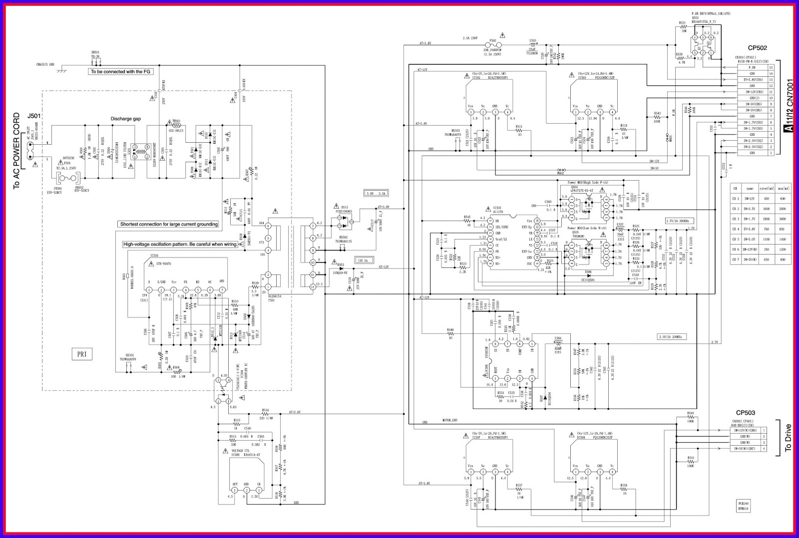
CLICK ON THE IMAGE TO ZOOM IN