REPAIRING AND NOT THROWING AWAY

Richtige Fernseher haben Röhren!

Richtige Fernseher haben Röhren!

In Brief: On this site you will find pictures and technical information about Service Modes, Circuit Diagrams, Firmware Update procedure, Disassemble procedure, Universal remote control set-up codes, Troubleshooting and more....

If you go into the profession, you will obtain or have access to a variety of tech tips databases HERE IT IS Master Electronics Repair !.

These are an excellent investment where the saying: 'time-is-money' rules. However, to learn, you need to develop a general troubleshooting approach - a logical, methodical, method of narrowing down the problem. A tech tip database might suggest: 'Replace C536' for a particular symptom. This is good advice for a specific problem on one model. However, what you really want to understand is why C536 was the cause and how to pinpoint the culprit in general even if you don't have a service manual or schematic and your tech tip database doesn't have an entry for your sick TV or VCR.

While schematics are nice, you won't always have them or be able to justify the purchase for a one-of repair. Therefore, in many cases, some reverse engineering will be necessary. The time will be well spent since even if you don't see another instance of the same model in your entire lifetime, you will have learned something in the process that can be applied to other equipment problems.
As always, when you get stuck, checking out a tech-tips database may quickly identify your problem and solution.In that case, you can greatly simplify your troubleshooting or at least confirm a diagnosis before ordering parts.

Happy repairing!
Today, the West is headed for the abyss. For the ultimate fate of our disposable society is for that society itself to be disposed of. And this will happen sooner, rather than later.

How to use the site:

- If you landed here via any Search Engine, you will get what you searched for and you can search more using the search this blog feature provided by Google. You can visit more posts scrolling the left blog archive of all posts of the month/year,
or you can click on the main photo-page to start from the main page. Doing so it starts from the most recent post to the older post simple clicking on the Older Post button on the bottom of each page after reading , post after post.

You can even visit all posts, time to time, when reaching the bottom end of each page and click on the Older Post button.

- If you arrived here at the main page via bookmark you can visit all the site scrolling the left blog archive of all posts of the month/year pointing were you want , or more simple You can even visit all blog posts, from newer to older, clicking at the end of each bottom page on the Older Post button.
So you can see all the blog/site content surfing all pages in it.

- The search this blog feature provided by Google is a real search engine. If you're pointing particular things it will search IT for you; or you can place a brand name in the search query at your choice and visit all results page by page. It's useful since the content of the site is very large.

Note that if you don't find what you searched for, try it after a period of time; the site is a never ending job !

..............The bitterness of poor quality is remembered long after the sweetness of todays funny gadgets low price has faded from memory........ . . . . . .....
Don't forget the past, the end of the world is upon us! Pretty soon it will all turn to dust!

©2010, 2011, 2012, 2013, 2014 Frank Sharp - You do not have permission to copy photos and words from this blog, and any content may be never used it for auctions or commercial purposes, however feel free to post anything you see here with a courtesy link back, btw a link to the original post here , is mandatory.
All posts are presented here for informative, historical and educative purposes as applicable within fair use. NOTHING HERE IS FOR SALE !

Wednesday 27 March 2019

SAMSUNG WS23Z30HP _ DISASSEMBLE PROCEDURE

SAMSUNG WS23Z30HP _ DISASSEMBLE PROCEDURE


BACK COVER

  1. Remove the 12 screws fixing the Back Cover.: RH, +, B, M4, L15, ZPC(BLK), SWRCH18A
  2. Tap the upper part of the Back Cover 2 or 3 times and pull the Back Cover to separate it from the unit.
  3. Lift the fixing Chassis up and pull the Back Cabinet to separate it from the unit.

Notice: Disassemble the product after disconnecting the power cord and discharge the unit to prevent an electric shock and damage to the product due to static electricity.


  • Remove the power cord fixing the back cover


  • Separate the Main chassis from the Front Cabinet.
  • Pull the Chassis lifting the fixing clip up.

Notice: Pulling the Chassis by force may damage the clip or the connector. Pull the Chassis just until the clip comes off the hole.
  • Separate the Speakers, the Side AV Wire, the Front Control from the Feature Box Board.
  • Separate the wire from the Wire fixing holder.
  • Since there is a clip to connect the Connector Header in the Wire Connector, pulling it by force may damage the clip or the connector. Press the clip down completely and pull the Connector.
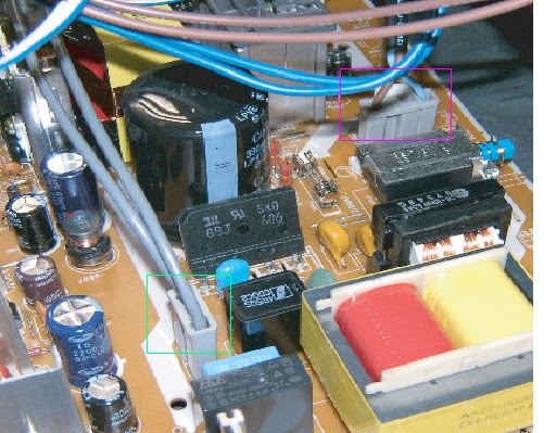
  • Separate the D-Coil and power cable from the Front Cabinet and Power Board.
  • To separate the power cord, slide the fixing clip and lift the cable up.
  • Separate the CRT Ass'y from the CRT.
  • Separate the TBC wire, GND, VM and Tilt cables from the CRT Ass'y sequentially.
  • Separate the cables connecting the FBT and the CRT.
  • Notice: Since there may be a remaining high-voltage current within the CRT, take care not to touch the CRT hole with metal or a part of yourself when separating the cables.
  • Separate the cables from the Feature Box/Main Board and CRT Ass'y.
  • Separate the wires from the FBT of the Deflection Board and the CRT Ass'y.
  • To separate the thick red and white wires, pull the wires while pressing the push-type clip at the connector.
  • To separate the thin red wire, insert a pin in the small hold next to the hole and pull the wire.
  • Notice: Take care when separating the wires because pulling the wires by force may damage the socket. In addition, separate the wires on a flat and clean surface so as to prevent scratching of the material and the PCB.
  • Separate the 8 pin cable from the CRT Assy's.
  • Separate the 14 pin cable from the Feature Box.

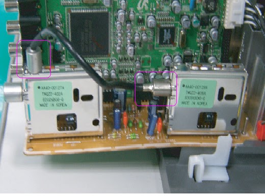
  • Separate the cable from the Splitter and the Tuner.
  • First separate the cable from the Splitter using a tool such as nippers.
  • Since pulling the wire by force may damage the coating of the wire, separate the wire holding the metal part with the tool.
  • Remove the DY Connector from the Main Board.