YAMAHA YST-SW515 DISASSEMBLING IDLE CURRENT ADJUSTMENT AND CIRCUIT DIAGRAM

YAMAHA YST-SW515
DISASSEMBLING IDLE CURRENT ADJUSTMENT AND CIRCUIT DIAGRAM
DISASSEMBLY PROCEDURES
(Remove parts in the order as numbered.)
Disconnect the power cable from the AC outlet.
Removal of Driver
a. Remove 4 screws (1) and then remove the Base.
b. Remove 4 screws (2) and then remove the Driver.
c. Disconnect the connector connected to the terminal of the Driver.
Disconnect the power cable from the AC outlet.
Removal of Driver
a. Remove 4 screws (1) and then remove the Base.
b. Remove 4 screws (2) and then remove the Driver.
c. Disconnect the connector connected to the terminal of the Driver.

Removal of Front Panel Ass'y
a. Remove 4 screws (3).
* Use an Allen wrench (2.5mm) to unscrew the Front Panel.
b. Pull out the front panel and disconnect the connector (CB4).
a. Remove 4 screws (3).
* Use an Allen wrench (2.5mm) to unscrew the Front Panel.
b. Pull out the front panel and disconnect the connector (CB4).

Removal of Rear Panel Ass'y
a. Remove 8 screws (4).
* Screws (4) are identified with arrow marks ( <= ).
b. Pull out the rear panel.
c. Remove 2 screws (5).
* Screws (5) are identified with arrow marks (<= ).
d. Remove the cover.
e. Disconnect the connectors (CB9 and CB10).
a. Remove 8 screws (4).
* Screws (4) are identified with arrow marks ( <= ).
b. Pull out the rear panel.
c. Remove 2 screws (5).
* Screws (5) are identified with arrow marks (<= ).
d. Remove the cover.
e. Disconnect the connectors (CB9 and CB10).

When Checking the P.C.B.:
# Connect all the connectors removed during disassembly back to the original positions.
# Spread cloth first and place the rear panel on it.
# Connect all the connectors removed during disassembly back to the original positions.
# Spread cloth first and place the rear panel on it.

ADJUSTMENTS
Confirmation of Power Amp operation
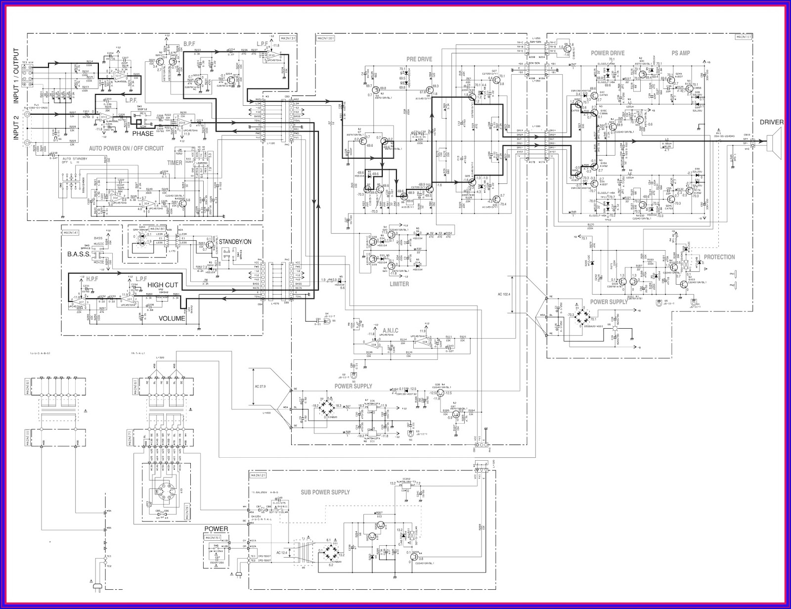
For the power amplifier which has been repaired, it is absolutely necessary to confirm that a correct waveform is obtained at points indicated by A and B in the schematic diagram according to the following procedure.
Devices required
Signal generator 8 Ohm or 6 Ohm load resistor Oscilloscope (dual trace type)
Connection
1) Connect the output signal from the signal generator to the input terminal of the unit.
2) Disconnect the connector terminal connected to the speaker unit and reconnect it to the load resistor.
3) Connect the HOT side of the oscilloscope CH1 probe to the point A or B indicated in the figure and the GND side to the GND of the main unit.
4) Connect the oscilloscope CH2 input to the red side of the connector cable, which is connected with the load resistor.
At this time, the GND terminal of CH2 must be left unconnected.
Setting
1) Set the signal generator to the sine wave, 100 Hz and minimum output level settings.
2) Set the volume of the unit to the minimum position.
3) Turn on the power to the unit.
4) Adjust the output level of the signal generator and the volume of the unit so that the output level observed at oscilloscope CH2 is 28 Vp-p.
Waveform observation
With the settings made as described above, observe
the waveform obtained at CH1 for judgment.
Confirmation of Power Amp operation
For the power amplifier which has been repaired, it is absolutely necessary to confirm that a correct waveform is obtained at points indicated by A and B in the schematic diagram according to the following procedure.
Devices required
Signal generator 8 Ohm or 6 Ohm load resistor Oscilloscope (dual trace type)
Connection
1) Connect the output signal from the signal generator to the input terminal of the unit.
2) Disconnect the connector terminal connected to the speaker unit and reconnect it to the load resistor.
3) Connect the HOT side of the oscilloscope CH1 probe to the point A or B indicated in the figure and the GND side to the GND of the main unit.
4) Connect the oscilloscope CH2 input to the red side of the connector cable, which is connected with the load resistor.
At this time, the GND terminal of CH2 must be left unconnected.
Setting
1) Set the signal generator to the sine wave, 100 Hz and minimum output level settings.
2) Set the volume of the unit to the minimum position.
3) Turn on the power to the unit.
4) Adjust the output level of the signal generator and the volume of the unit so that the output level observed at oscilloscope CH2 is 28 Vp-p.
Waveform observation
With the settings made as described above, observe
the waveform obtained at CH1 for judgment.
Idling Adjustment
To stabilize operation of the amplifier, turn ON the power with no input signal and wait for 2 to 3 minutes in non loaded condition before the adjustment. Confirm that the voltage across the terminals TP11 and TP12 is 10 mV to 200 mV. If it exceeds 200 mV, open (cut off) R172.
Confirmation of AUTO STANDBY operation Setting
1) Turn off the power switch located on the rear panel.
2) In order to shorten the time required for operation check; connect a 10kOhm resistor at both ends of R252 on the MAIN P.C.B.
3) Connect the output signal from the signal
generator to the INPUT 2 / L/MONO terminal of the unit.
4) Set the signal generator for the sine wave of 100Hz, 8mV.
5) Turn on the power switch located on the rear panel.
Confirmation
1) Set the AUTO STANDBY switch to the LOW position.
4) Set the signal generator for the sine wave of 100Hz, 8mV.
5) Turn on the power switch located on the rear panel.
Confirmation
1) Set the AUTO STANDBY switch to the LOW position.
2) Turn on the STANDBY/ON switch.
The display LED lights up (green) and its color changes to red after 4 to 5 seconds.
3) Turn off the STANDBY/ON switch.
The display LED goes off.
4) Set the AUTO STANDBY switch to the HIGH position.
The display LED lights up (green) and its color changes to red after 4 to 5 seconds.
3) Turn off the STANDBY/ON switch.
The display LED goes off.
4) Set the AUTO STANDBY switch to the HIGH position.
5) Turn on the STANDBY/ON switch.
The display LED lights up (green) and its color remains unchanged even after time have elapsed.
6) Turn off the STANDBY/ON switch. The display LED goes off.
After confirmation
1) Turn off the power switch.
2) Disconnect the 10kOhm resistor connected to both ends of R252.
The display LED lights up (green) and its color remains unchanged even after time have elapsed.
6) Turn off the STANDBY/ON switch. The display LED goes off.
After confirmation
1) Turn off the power switch.
2) Disconnect the 10kOhm resistor connected to both ends of R252.
CIRCUIT DIAGRAM