REPAIRING AND NOT THROWING AWAY

Richtige Fernseher haben Röhren!

Richtige Fernseher haben Röhren!

In Brief: On this site you will find pictures and technical information about Service Modes, Circuit Diagrams, Firmware Update procedure, Disassemble procedure, Universal remote control set-up codes, Troubleshooting and more....

If you go into the profession, you will obtain or have access to a variety of tech tips databases HERE IT IS Master Electronics Repair !.

These are an excellent investment where the saying: 'time-is-money' rules. However, to learn, you need to develop a general troubleshooting approach - a logical, methodical, method of narrowing down the problem. A tech tip database might suggest: 'Replace C536' for a particular symptom. This is good advice for a specific problem on one model. However, what you really want to understand is why C536 was the cause and how to pinpoint the culprit in general even if you don't have a service manual or schematic and your tech tip database doesn't have an entry for your sick TV or VCR.

While schematics are nice, you won't always have them or be able to justify the purchase for a one-of repair. Therefore, in many cases, some reverse engineering will be necessary. The time will be well spent since even if you don't see another instance of the same model in your entire lifetime, you will have learned something in the process that can be applied to other equipment problems.
As always, when you get stuck, checking out a tech-tips database may quickly identify your problem and solution.In that case, you can greatly simplify your troubleshooting or at least confirm a diagnosis before ordering parts.

Happy repairing!
Today, the West is headed for the abyss. For the ultimate fate of our disposable society is for that society itself to be disposed of. And this will happen sooner, rather than later.

How to use the site:

- If you landed here via any Search Engine, you will get what you searched for and you can search more using the search this blog feature provided by Google. You can visit more posts scrolling the left blog archive of all posts of the month/year,
or you can click on the main photo-page to start from the main page. Doing so it starts from the most recent post to the older post simple clicking on the Older Post button on the bottom of each page after reading , post after post.

You can even visit all posts, time to time, when reaching the bottom end of each page and click on the Older Post button.

- If you arrived here at the main page via bookmark you can visit all the site scrolling the left blog archive of all posts of the month/year pointing were you want , or more simple You can even visit all blog posts, from newer to older, clicking at the end of each bottom page on the Older Post button.
So you can see all the blog/site content surfing all pages in it.

- The search this blog feature provided by Google is a real search engine. If you're pointing particular things it will search IT for you; or you can place a brand name in the search query at your choice and visit all results page by page. It's useful since the content of the site is very large.

Note that if you don't find what you searched for, try it after a period of time; the site is a never ending job !

..............The bitterness of poor quality is remembered long after the sweetness of todays funny gadgets low price has faded from memory........ . . . . . .....
Don't forget the past, the end of the world is upon us! Pretty soon it will all turn to dust!

©2010, 2011, 2012, 2013, 2014 Frank Sharp - You do not have permission to copy photos and words from this blog, and any content may be never used it for auctions or commercial purposes, however feel free to post anything you see here with a courtesy link back, btw a link to the original post here , is mandatory.
All posts are presented here for informative, historical and educative purposes as applicable within fair use. NOTHING HERE IS FOR SALE !

Showing posts with label CHARGER. Show all posts

Wednesday, 14 October 2020

MOBILE CELL PHONE CHARGER CIRCUIT SCHEMATIC DIAGRAM

 The main part of the circuit mobile cellphone charger is timer IC NE555, used to charge and monitor the voltage level. IC1 get control voltage to pin 5 by zener diode ZD1­. Threshold pin 6 and trigger pin 2 is supplied with a voltage set by VR1 and VR2 respectively. The trigger pin 2 of IC1 is below 1/3VCC when discharge battery is connected to the circuit as a result flip-flop of IC1 is switched on to take output pin 3 high. The process is reversed when battery is fully charged of charged battery is connected. Here transistor T1 used to enhance the charging current from output pin 3 of IC1. Adjust potentiometer VR1 and VR2 as per require.

LED status for different charging conditions

Load across the outputOutput frequency (at pin 3)LED1
No battery connected765 kHzOn
Charging battery4.5 HzBlink
Fully charged battery0Off
Circuit Diagram

Parts
Resistors (all ¼-watt, ± 5% Carbon)
R1 = 390 Ω
R2 = 680 Ω
R3 = 39 Ω/1W
R4 = 27 KΩ
R5 = 47 KΩ
R6 = 3.3 KΩ
R7 = 100 Ω/1W
VR1, VR2 = 20 KΩ
Capacitors
C1 = 0.001 µF (ceramic disc)
C2 = 0.01 µF (ceramic disc)
C3 = 4.7 µF/25V (Electrolytic )
Semiconductors
IC1 = NE555 timer IC
T1 = SL100 or any Medium power general purpose NPN transistor like: 2N4922 , 2N4921,2N4238, FCX1053A
ZD1 = 5.6 V/1W
LED1
Miscellaneous 
SW1 = On/off switch
1.5V*8 AA cells
Mobile connector

Source- http://electronicsproject.org/mobile-cellphone-charger/

BATTERY CHARGER WITH BUILT IN PROTECTION CIRCUIT DIAGRAM

IT  is a circuit for a battery charger with automatic overload protection feature.  

The power supply is 9V and is stabilized by a voltage regulator IC LM317.  

The regulator output is used to charge the 6V battery.  

Once the battery is fully charged (ie the voltage across the battery is 6V) enters the zener diode biased and starts conducting, which gives a positive voltage to the base terminal of BC548  loading.


 Battery Charger with Protection Circuit Diagram


Battery Charger with Protection Circuit Diagram

Sunday, 28 June 2020

IPHONE USB CHARGER PINOUT DESCRIPTION

 Description : 4 resistors with this values: 2 of 50 kΩ, 1 of 100 kΩ and 1 of 150 kΩ.

Tuesday, 18 February 2020

UNIVERSAL CHARGER FOR LEAD-ACID BATTERIES 12V, 1 ... 30AH

A device for charging small lead-acid (gel) batteries. The design has a number of very valuable functions that are rarely found in other chargers. First of all, it is that the device prevents overcharging the battery. When the battery is charged, the charge current automatically decreases. If a 230 V mains failure occurs during charging, the device will not discharge the battery. The charger can work as a power source.  12v, 1...30Аh

Characteristic
 charging 12 V lead acid batteries
 battery capacity: 1 ... 30 Ah
 charging system alarm: two-color LED diode
 sound signal of wrong polarity
 power source: 11 ... 13 V (the power of the transformer should be at least 50% than the power obtained by multiplying the charging current and voltage of 15 V)

Circuit description
The device is used to charge small lead-acid batteries. The device can also work with the battery as a buffer power source, providing uninterrupted power to devices.


The presented circuit has a number of very valuable functions rarely found in chargers. Primarily:
 Prevents battery overcharging. When the battery is fully charged, the charging current drops to a negligible value, so even multi-day charging is not terrible.

 Loss of mains voltage during charging will not lead to a rapid discharge of the battery - then the discharge current is about 2.5 mA.
 The charger is not afraid of reverse battery connection. Most chargers with a reverse battery connection can be damaged by the huge current flowing through the output circuits.
 The circuit is also not afraid of a short circuit of the output terminals of the charger.
 A two-color LED indicates the operating status, and smooth changes from red to green reflect the charging process.
All these functions are implemented in a very simple scheme containing several popular and cheap elements.
Pay attention to the correct soldering of the terminals of the buzzer Y1, which is designed to work with a battery connected in the opposite direction. The charging current should be selected depending on the capacity of the rechargeable battery. It is very easy. It is necessary to solder 1-ohm resistors (indicated on the RS circuit) to obtain the necessary current. One RS resistor with a value of 1 Ω provides a charging current of approximately 0.15 A. For example, for a 2 Ah gel cell, the maximum charging current is 0.6 A (0.3 · 2), so you need to solder four RS resistors per 1 Ohm. After assembling and checking the entire battery, connect the battery to terminals P, N. When charging a discharged battery, the current on it will be immediately large, but after a while it will stabilize to a value determined by the active resistance PR1. Use potentiometer PR1 to adjust the final charge voltage. If the charger will operate in uninterrupted power mode (constantly on and connected to the battery), then PR1 should set the final voltage to about 13.8 V (13.5 ... 13.8 V), which corresponds to a value of 2.25 ... 2.3 In per element, guaranteeing the expected durability. During cyclic operation (alternate charging and discharging), the final voltage on the battery should be about 15 V (14.4 ... 15 V). This voltage value is not critical here. The higher the voltage, the faster the battery will charge. However, leaving the battery continuously under a voltage of more than 15 V. can shorten its life. Soldering the corresponding number of RS resistors per 1 Ohm and setting the potentiometer PR1 are the only necessary settings.
For transistor T1, you need to choose the appropriate radiator. Its size will depend on the charging current and voltage of the transformer. At low currents, a piece of aluminum sheet may suffice. 12 1-ohm resistors will give a maximum current of 2A. For this, the radiator must be appropriate. During operation, such a radiator can be very hot - up to +90 ... 100 C. When choosing a charging current, remember that it should not exceed numerically 0.3 C (C is the battery capacity in ampere-hours). At 0.3 C, a full charge will be approximately 6 hours. For example, for a battery with a capacity of 10 ampere-hours (10 A · h), the charging current should not exceed 3 A (0.3 · 10 A · h). Some manufacturers give a maximum charging current of 0.25C. Of course, the charging current can be reduced to 0.1 C or even 0.05 C, but then the charging time will drastically increase, even up to tens of hours. The value of the charging current determines the resulting resistance of the resistors RS1 ... RS4.

The circuit diagram (Fig. 1) shows four RS resistors. Four groups are provided on the sample board to solder up to 12 resistors. This method was used intentionally because it makes it very easy to select a charging current. The power transformer used must have a nominal (alternating) voltage of 12 ... 15 V. Its power will depend on the required charging current. The power of the transformer must be at least 50% higher than the power obtained by multiplying the charging current and a voltage of 15 V. For example, for a charging current of 0.6 A, the product of 0.6 A · 15 V is 9 W, so the power of the transformer should not be less than 13.5 watts (150% * 9 watts).

Details


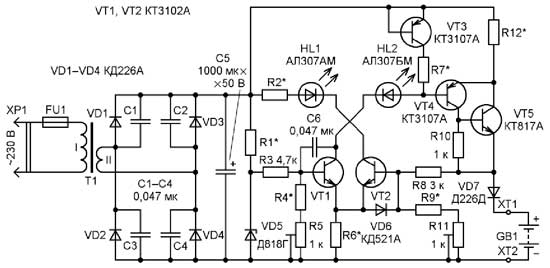
AUTOMATIC BATTERY CHARGER

Back in 1991, I purchased a Meridian RP-248 radio. He was powered by a built-in battery composed of four 316 galvanic cells or TsNK-045 batteries (in modern terminology - size AA). To power the receiver from the batteries, a power supply unit was needed that could charge them with rated current for the time required to fully charge.
For the convenience of using a receiver powered by a battery of batteries, a contact was disconnected in it with a jumper disconnecting the internal battery when an external power source was connected, it became possible to charge the batteries without removing them from the receiver. For batteries, charging conditions are defined: this is 0.1Q current (Q is the nominal capacity of the battery) for 15 hours (the voltage on each battery at the end of charging is 1.5 V). As a rule, it is not possible to monitor this; a need arises for an automatic charger (AZU), which does not require any attention, working on the principle of “turned on and forgot”. To do this, the charger must provide the specified charging mode until the voltage reaches 1.5 V on each battery, then reduce the charging current to 0.01 ... 0.02 Q and remain in this state for an unlimited time, keeping the battery (battery) always ready for use. work [1]. It will be convenient if the operating mode of the AZU will be displayed by a light indication. Based on this task, an automatic device was developed (Fig. 1), containing a minimum of parts for widespread use - all in all, four transistors were required, which at that time were outdated, but suitable in terms of parameters for working in this device.

The device has been working to this day, and it has been constantly on for at least about the last 20 years. A radio already with a remodeled VHF band is used daily as a radio point in the kitchen. Practice confirms the high reliability of semiconductor devices, unless they work in transcendental modes and have no factory defects or fakes. However, when assembling the device, it is necessary to check and measure the parameters of each element, especially oxide capacitors, which are the most unreliable elements. When repeating this device, you can apply many other transistors and diodes, whose maximum permissible parameters exceed the values in force in the device.
The power supply of the AZU from the network is carried out through a step-down transformer, which ensures electrical safety, followed by a rectifier bridge VD1 -VD4. If the AZU will be used to power the radio, then to eliminate the so-called multiplicative background, the diodes should be bridged with ceramic capacitors. Capacitor C1 smoothes the ripple of the rectified voltage, its capacitance should be at least 1000 μF for every 100 mA of current consumption. The reference voltage (9 V) is removed from the precision Zener diode VD5. Resistor R1 determines its rated stabilization current (10 mA). The voltage limitation on the battery (battery) upon reaching full charge is carried out by the differential cascade VT1VT2 as follows. The set voltage, at which it is necessary to limit the charging current, is determined by the voltage divider R2R3 and applied to the base of the transistor VT1, and the base VT2 receives voltage from the battery, taking into account the voltage drop across the diode VD7, which disconnects the battery from the battery when the voltage fails. Until the battery is charged, the voltage based on VT2 is less than that based on VT1, and therefore, VT2 is closed and the HL2 LED does not light. HL1 is on because VT1 is in active mode. The current value is determined by the resistance of the resistor R5 and the voltage based on VT1 and does not depend on the voltage on its collector. Such a circuit is known as a current source (IT) [2]. Consequently, the voltage drop across the resistor R4 will be stable, and HL1 will glow, indicating that the battery is charging. Its charging current is stable and does not depend on the voltage on the battery, since transistors VT3 and VT4 form IT.
Particular accuracy in maintaining the charging current is not required; limiting the battery voltage when reaching full charge is crucial. The accuracy of the differential stage and the parametric voltage regulator is quite enough to solve this problem. When the voltage on the battery corresponding to the full charge is reached, the transistor VT2 goes into active mode, its collector current appears, the HL2 LED lights up, indicating that the battery is charged, the current through VT1 will decrease, and the charge current will decrease to 0.01 ... 0.02Q, which eliminates battery recharging and damage. Capacitor C2 eliminates possible self-excitation, resistor R6 reduces the voltage across the VT2 collector, and therefore the power dissipated by it. The VD6 diode provides reliable closing of the VT4 transistor.

The VT4 transistor can be replaced by any of the KT973, KT814, KT816 series and others (taking into account the charging current and the power dissipated in this case), VT3 - by any transistor from the KT3102, KT315, KT503 series, and VT1, VT2 - by any of the KT203, KT208, KT209 series KT502. The current transfer coefficient of the base of transistors is not less than 50.
If you need to charge the battery with large capacities and (or) voltages, you can assemble the battery according to the scheme shown in Fig. 2, using transistors of a different structure as more common. An exemplary voltage and a comparison with it is supplied to the base of the transistors of the differential stage through dividers or directly, depending on the voltage of the battery. So, if its voltage is less than 9 V (stabilization voltage D818 = 9 V), then the resistors R9, R11 are excluded, the voltage is supplied to the VT2 base through the resistor R8, and the required value of the battery charging end voltage is set by the divider R3R4R5.


If the battery voltage is more than 9 V, then the resistors R4, R5 are excluded, and the charging end voltage is set by the divider R8R9R1 1. The current of the dividers is selected in the range of 0.5 ... 1 mA. The resistor R6 sets the charging current of about 10 mA after determining the voltage on the basis of the transistor VT1. By choosing a resistor R1, the nominal stabilization current of the Zener diode VD5 is set to 10 mA. The VD6 diode limits the reverse voltage at the VT2 emitter junction, which can occur during a short circuit in the battery circuit.
Transistors VT3, VT4, VT5 form a powerful current source [2]. Thanks to the first of them, the voltage drop across the resistors R7, R12 can be set on the order of 1 V, which may be required if the battery voltage is comparable with the voltage at the output of the rectifier. With a battery voltage of less than 9 V, the VT3 transistor can be excluded, and the voltage drop across the resistors R7, R12 should be selected equal to several volts, while the power dissipated by the transistor VT5 will decrease, but a resistor R12 with a correspondingly higher dissipation power will be required.
The power and voltage on the secondary winding of the step-down transformer T1, the electrical parameters of the diodes VD1-VD4, VD7, transistor VT5 are determined by the capacity and voltage of the battery. To ensure long trouble-free operation of the device, the limit values of the parameters of semiconductor devices and resistors must exceed the values existing in the device by 2 ... 3 times. If it is assumed that the device will work around the clock without supervision, special attention should be paid to fire safety. The transformer must be of sufficient power, with reliable insulation and low idle current, indicating the absence of saturation of the magnetic circuit and a sufficient number of turns of the primary winding. To determine the maximum permissible mains voltage and identify short-circuited turns it is useful to take off the magnetization characteristic of the transformer (the dependence of the open-circuit current on the voltage on the mains winding). A sharp increase in the open-circuit current is permissible only when the voltage on the winding exceeds the rated mains by 10% (with a nominal 230 V it is 253 V), which indicates a sufficient number of turns of the primary winding. The housing of the control unit must also meet the requirements of fire and electrical safety.
When setting up, the rectifier of the AZU should be loaded with a current of 0.01 ... 0.02 Q and the nominal charging current (approximately 10 mA) should be set by selecting resistor R6, since it is in this mode that the charging current should be limited. Then, depending on the voltage of the battery, select the configuration of the circuit of the device and pre-set the voltage limiting the charging of the battery. If this voltage is more than 9 V, then, according to the above, the base of the transistor VT1 is connected to the zener diode VD5 through the resistor R3, in this case the voltage on its emitter will be less than about 0.65 V, i.e. about 8.4 V. Therefore , at a current of about 10 mA, the nearest value of the resistor R6 is 820 Ohms. Then determine the values of the resistors R7, R12 and the need for a transistor VT3 to achieve the required charging current. When measuring the charging current, the HL1 LED should not light. To perform this work, the AZU is loaded with a chain according to the scheme in Fig. 3. Next, the tuning resistor R11 sets the current to 0.01 ... 0.2Q with a voltage at the output of the AZU corresponding to 1.5 V for each battery of the battery.

If the battery voltage is less than 9 V, then R9, R11 are excluded, using the dividers R3R4R5, the voltage corresponding to the charged battery plus the voltage drop across the VD7 diode is pre-set, then, according to the above, the resistance of the resistors R6, R7, R12 is determined and the charge limiting voltage is finally set Battery trimmer resistor R5.

Literature
 A little bit about charging nickel-cadmium batteries. - Radio, 1996, No. 7, p. 48.
 Semushin S. Sources of current and their application. - Radio, 1978, No. 1, p. 39; No. 2, p. 44.
Author: S. Tikhonov, the city of Kaltan, Kemerovo region


CHARGER FOR NI-MH BATTERY

The reason for the development and manufacture of the proposed device was the desire to replace the galvanic power element of the wall electromechanical clock with a battery. The available charger allowed charging only an even number of batteries, and one AA-size Ni-MH battery needed to be charged.
When viewing the literature, I was interested in “Automatic Battery Charger” described by N. Skrindevsky in Radio, 1991, No. 12, p. 28-30. I liked the idea embedded in this design to charge the battery cyclically, alternating charging intervals with intervals measuring the emf of the battery. As a result of prototyping and debugging, the proposed charger was obtained.
Key Specifications
Supply voltage, V ............. 5
Charging current, mA …………… ..150
The threshold for switching off the charging current, V ………………… 1.38
The threshold for switching on the charging current, V …………………… .. 1
The duration of the charging cycle, s .............................. 40
Duration of measurement, s ……… 1
A diagram of this device is shown in Fig. 1. A current source is assembled on the transistor VT2, resistors R9-R12 and LED HL1. It is controlled by transistor VT1. The HL1 LED has two functions: it serves as a source of stable voltage supplied to the base of transistor VT2 through resistor R10, and at the same time as a battery indicator. Resistors R11 and R12 set the charging current, the value of which in milliamperes is chosen numerically equal to the nominal battery capacity G1 in milliampere-hours. Resistor R9 limits the current through the LED HL1. The VD2 diode prevents the discharge of the G1 battery through the charger in the event of a power failure or a power outage.


On a voltage comparator DA1.1, resistors R1-R6, capacitor C1 and diode VD1, a pulse sequence generator with a duration of 40 s with a pause of 1 s is assembled. In the pauses between pulses, the EMF of the battery is measured.
During the measurement, the current source is disconnected from the rechargeable battery. At this time, the voltage on the battery is compared with the model voltage - the one to which the battery needs to be charged. The diode VD4 prevents the blocking voltage from reaching the engine trimmer resistor R14.
On the voltage comparator DA1.2 and resistors R13-R17, a Schmitt trigger is assembled, which controls the voltage on the rechargeable battery. For the trigger to work correctly, a blocking voltage is supplied to the inverting input of the comparator DA1.2 from the output of the comparator DA1.1 during charging through the VD3 diode.
Upon reaching the voltage on the battery set by the tuning resistor R14 and applied to the inverting input of the comparator DA1.2, a high level voltage appears at the output of the last one, which is fed through the diode VD5 to the inverting input of the comparator DA1. 1, blocking the operation of the generator. At the output of the comparator DA1.1, a low voltage level is set, the transistor VT1 closes, the LED HL1 goes out.
At the same time, a high level voltage from the output of the comparator DA1.2 is also supplied to the base of the transistor VT3, opening it, the HL2 LED turns on, signaling the completion of battery charging. The reference voltage at the inverting input of the comparator DA1.2 is chosen equal to 1.38 V - the same as that of an available industrial charger.
The LM393N chip can be replaced with K1401CA3A or another of its many analogues, and KT312V transistors can be replaced with similar ones with other letter indices or with KT315 series transistors. Replacement of the KT816V transistor can be the KT814V. Instead of D223 diodes, D220 or the KD522 series are suitable, and instead of KD226A, any rectifier diode with a permissible forward current of at least 200 mA is suitable. When replacing the AL307 series LEDs with more modern ones, it is recommended to increase the values of the resistors R9 and R20 in order to reduce the brightness of their glow to an acceptable level.

Oxide capacitors C1, C2 - imported or domestic series K50-16, K50-35. Capacitors C3 and C4 - any ceramic or film. Trimmer resistor R14 - imported. Fixed resistors - MLT-0.125 or similar.
The charger is assembled in a small housing from the dental handpiece. With the lid open, it is shown in fig. 2. Initially, it was planned to place the battery holder (contacts X1 and X2) directly on the printed circuit board, and the board was designed specifically for this location. Subsequently, the holder was glued into the housing cover.


The drawing of the circuit board of the charger is shown in Fig. 3. For the LM393N chip, a panel is installed on it. Permanent resistors are installed both parallel and perpendicular to the surface of the board. One of the pins of resistor R2 and pin
the cathode of the diode VD1 is soldered into the board, and the remaining free conclusions of these elements are connected above it. The battery holder and LEDs glued into the housing cover are connected to the board by flexible insulated mounting wires.


In a properly assembled device, you only need to adjust the battery charging current and charging disconnect voltage. Before setting the charging current, the DA1 chip must be removed from the panel, and instead of a battery, connect a 33 Ohm resistor or a miniature incandescent lamp MN 6.3-0.3 to the terminals X1 and X2 through a multimeter in the direct current measurement mode with a limit of at least 200 mA. A selection of resistors R11, R12 should set the multimeter to 150 mA. But you can set another charging current, depending on the capacity of the battery.
Adjusting the voltage to turn off the battery charging is reduced to setting the trimmer resistor R14 voltage of 1.38 V between sockets 2 and 4 of the comparator panel. After that, you need to disconnect the device from the power source and insert the chip into the panel. The charger is ready to use.
The width of the trigger hysteresis loop on the comparator DA1.2 depends on the ratio of the resistance of the resistors R15 and R16. Decreasing the resistance of resistor R15 increases the trigger voltage.

Author: G. Kosolapov, Kirovo-Chepetsk, Kirov Region

Tuesday, 23 April 2019

MAKITA CORDLESS POWER DRILL DC7100

Makita Cordless Power Drill DC7100


The Makita Cordless Power Drill is a handy tool.  Its power unit consists of a 7.2 volt battery pack and a fast battery charger.   This article describes how to replace the battery and repair the battery charger.


 What’s Needed

1)     For replacement of battery 


a)     Soldering iron,  solders and some connecting wires


b)     4 Nos  of 18650 Li-ion batteries.  Can also use some of the good batteries in Laptop for this purpose


c)     Remove the end cap of the battery pack and withdraw the batteries


d)     Solder the 18650 batteries,  2 in parallel then put them in series to make up a total voltage of 7.4 volts.  Pay particular attention to positive and negative battery terminal and make sure there are correctly wired;  also pay attention to how the resistor is connected. 


e)     Once soldering is completed, wrap the batteries with shrinkable plastic and re-assembled the batteries to the battery pack casing.


2)     For repair of the power charger 


In addition to the soldering iron,   one will need a multimeter that can measure the workings of the A1015 transistor and the 2P4M SCR thyristor.  These 2 components are likely to be at fault.  .  One would need knowledge of electronic repairs for this task.  Use the attached circuit diagram to troubleshoot.


2P4M Thyristor


Wednesday, 10 April 2019

LENOVO THINKPAD EDGE E550 - E555 – HOW TO TEST THE BATTERY CHARGER

Lenovo ThinkPad Edge E550 - E555 – How to test the battery charger

Lenovo ThinkPad Edge E550 - E555 – How to test the battery charger – How to remove the battery – How to test the battery pack – How to reset the Laptop
Lenovo ThinkPad Edge E550 - E555 
Power system checkout
To verify a power symptom, do the following:
1. Turn off the computer.
2. Connect the ac power adapter.
3. Turn on the computer. If the computer can be turned on, it means that either the battery pack or the ac power adapter is functional.
4. Insert a straightened paper clip into the emergency reset hole to reset the computer. If the computer is still powered on, it means that the ac power adapter is functional.
5. Turn off the computer.
6. Disconnect the ac power adapter and turn on the computer. If the computer can be turned on, it means that the battery pack is functional.
If you suspect a power problem, see the appropriate one of the following power supply checkouts:
“Checking the ac power adapter”
“Checking the built-in battery and operational charging”
“Checking the coin-cell battery”
Checking the ac power adapter
You are here because the computer fails only when the ac power adapter is used.
If the power problem occurs only when the docking station or the port replicator is used, replace the docking station or the port replicator.
If the system status indicator does not blink three times when an ac power source is connected, check the power cord of the ac power adapter for correct continuity and installation.
To check the ac power adapter, do the following:
1. Unplug the ac power adapter cable from the computer.
2. Measure the output voltage at the plug of the ac power adapter cable. See the following illustration:
Note: Output voltage of pin 2 of the ac power adapter might differ from the one you are servicing.
3. If the voltage is not correct, replace the ac power adapter.
4. If the voltage is acceptable, replace the system board.
Note: Noise from the ac power adapter does not always indicate a defect.
Checking the built-in battery and operational charging
This computer supports only batteries specially designed for this specific system and manufactured by Lenovo or an authorized builder. The system does not support unauthorized batteries or batteries designed for other systems. If an unauthorized battery or a battery designed for another systems is installed, the system will not charge.
To check for detailed battery status information, do the following:
For 7: Open the Power Manager program and click the Battery tab.
For 8.1: Open the Lenovo Settings program and click OK.
To check whether the battery charges properly during operation, do the following:
1. Discharge the battery until the remained battery power is less than 50%.
2. Connect the computer to ac power to charge the battery. If the battery status icon in the Windows notification area indicates that the battery is not charging, remove the battery and let it return to room temperature.
3. Reinstall the battery. If the battery is still not charging, replace the battery pack.
4. Check the battery status icon again. If the same error still exists, replace the system board.
Checking the coin-cell battery
To check the coin-cell battery, do the following:
1. Disconnect the battery connector.
2. Remove the coin-cell battery.
3. Measure the voltage of the coin-cell battery. See the following illustration.
If the voltage is correct, replace the system board.
If the voltage is not correct, replace the coin-cell battery.
If the coin-cell battery discharges quickly after replacement, replace the system board.
Performing a recovery operation
This section provides instructions on how to perform a recovery operation using the Rescue and Recovery program.
1. From the Windows desktop, click Start >All Programs > Lenovo ThinkVantage Tools > Enhanced
Backup and Restore. The Rescue and Recovery program opens.
2. In the Rescue and Recovery program main window, click the Launch advanced Rescue and Recovery arrow.
3. Click the Restore your system from a backup icon.
4. Follow the instructions on the screen to complete the recovery operation.
Resetting your computer to the factory default settings
If you want to recycle your computer or just start over, you can reset your computer to the factory default settings. Resetting the computer will reinstall the operating system, reinstall all the programs that came with your computer, and reset all the settings to the factory default settings.
Attention: If you reset the computer to the factory default settings, all your personal files and settings will be deleted. To avoid data loss, make a backup copy of all the data that you want to keep. To reset your computer to the factory default settings, do the following:
1. Move your pointer to the top-right or bottom-right corner of the screen to display the charms. Click Settings > Change PC settings > Update and recovery > Recovery.
2. In the Remove everything and reinstall Windows section, click Get started. Then click Next to confirm the operation.
3. Depending on your needs, do one of the following:
To perform a quick format, click Just remove my files to start the process. The process will take several minutes.
To perform a complete format, click Fully clean the drive to start the process. The process will take several hours.
4. Follow the instructions on the screen to reset your computer to the factory default settings.
Disassembling
Large bottom cover
Loosen the screws 1 and then remove the large bottom cover 2.
Small bottom cover
Loosen the screw 1 and then remove the small bottom cover 2

Thursday, 21 March 2019

DAEWOO DPC0720 - 7" LCD COLOR MONITOR & DVD PLAYER - BATTERY CHARGER & HV-BOARD - SCHEMATIC DIAGRAM - TROUBLESHOOTING CHART

DAEWOO DPC0720 - 7" LCD COLOR MONITOR & DVD PLAYER - BATTERY CHARGER & HV-BOARD - SCHEMATIC DIAGRAM - TROUBLESHOOTING CHART


BATTERY CHARGER [SCHEMATIC] {Click on images to Enlarge}
PCB [BATTERY CHARGER - TOP VIEW]
PCB [BATTERY CHARGER - FOIL SIDE]
HV-BOARD [SCHEMATIC DIAGRAM]
TROUBLESHOOTING CHART [LCD MONITOR PART]
TROUBLESHOOTING CHART [DVD PART]

Saturday, 16 March 2019

BLACK & DECKER VECO12BD - BATTERY CHARGER - SCHEMATIC - (CIRCUIT DIAGRAM)

BLACK & DECKER VECO12BD - BATTERY CHARGER - SCHEMATIC - (Circuit diagram)

SCHEMATIC DIAGRAM

CLICK ON SCHEMATIC TO ZOOM.

Tuesday, 12 March 2019

12V TRICKLE CHARGER ELECTRONIC PROJECT

12V TRICKLE CHARGER ELECTRONIC PROJECT

12V TRICKLE CHARGER ELECTRONIC PROJECT 

         The 12v Trickle Charger circuit uses a TIP3055 power transistor to limit the current to the battery by turning off when the battery voltage reaches approx 14v or if the current rises above 2 amp. The signal to turn off this transistor comes from two other transistors - the BC557 and BC 547. Firstly, the circuit turns on fully via the BD139 and TIP3055. The BC557 and BC 547 do not come into operation at the moment. The current through the 0.47R creates a voltage across it to charge the 22u and this puts a voltage between the base and emitter of the BC547. The transistors turn on slightly and remove some of the turn-on voltage to the BD139 and this turns off the TIP3055 slightly. This is how the 2 amp max is created. As the battery voltage rises, the voltage divider made up of the 1k8 and 39k creates a 0.65v between base and emitter of the BC557 and it starts to turn on at approx 14v. This turns on the BC 547 and it robs the BD136 of "turn-on" voltage and the TIP3055 is nearly fully turned off. All battery chargers in Australia must be earthed. The negative of the output is taken to the earth pin.

CLICK ON THE IMAGE TO ZOOM IN

LENOVO IDEA TAB S2110A DISASSEMBLING AND AC ADAPTER CHECKING

LENOVO IDEA TAB S2110A DISASSEMBLING AND AC ADAPTER CHECKING

DISASSEMBLING AND CHARGER TESTING 

Important notice for replacing a system board
Some components mounted on a system board are very sensitive. Improper handling can cause damage to those components, and may cause a system malfunction.
Attention: When handling a system board:
• Do not drop the system board or apply any excessive force to it.
• Avoid rough handling of any kind.
• Avoid bending the system board and hard pushing to prevent cracking at each BGA (Ball Grid Array) chipset
Checking the AC adapter
You are here because the computer fails only when the AC adapter is used.
• If the power-on indicator does not turn on, check the power cord of the AC adapter for correct continuity and installation.
• If the computer does not charge during operation, go to “Checking operational charging”.
To check the AC adapter, follow the steps below:
1. Unplug the AC adapter cable from the computer.
2. Measure the output voltage at the plug of the AC adapter cable. See the following figure:


Note: Output voltage for the AC adapter pin No. 2 may differ from the one you are servicing.
3. If the voltage is not correct, replace the AC adapter.
4. If the voltage is acceptable, do the following:
• Replace the system board.
Checking operational charging
To check whether the battery charges properly during operation, use a discharged battery pack or a battery pack that has less than 50% of the total power remaining when installed in the computer. Perform operational charging. If the battery status indicator or icon does not light on, remove the battery pack and let it return to room temperature. Reinstall the battery pack. If the charge indicator or icon is still off, replace the battery pack. If the charge indicator still does not light on, replace the system board. Then reinstall the battery pack. If it is still not charged, go to the next section
Checking the battery pack
Battery charging does not start until the Power Meter shows that less than 95% of the total power remains; under this condition the battery pack can charge to
100% of its capacity. This protects the battery pack from being overcharged or from having a shortened life. To check your battery, move your cursor to the Power Meter icon in the icon tray of the Windows® taskbar and wait for a moment (but do not click it), and the percentage of battery power remaining is displayed. To get detailed information about the battery, double-click the Power Meter icon.
Note: If the battery pack becomes hot, it may not be able to be charged. Remove it from the computer and leave it at room temperature for a while. After it cools down, reinstall and recharge it.
To check the battery pack, follow the steps below:
1. Turn off the computer.
2. Remove the battery pack and measure the voltage between battery terminals
1 (+) and 7 (-). See the following figure:


3. If the voltage is less than +11.0 V DC, the battery pack has been discharged.
Note: Recharging will be continued for at least 3 hours, even though the indicator does not light on.
If the voltage is still less than +11.0 V DC after recharging, replace the battery.
4. If the voltage is more than +11.0 V DC, measure the resistance between battery terminals 5 and 7. The resistance must be 4 to 30 KOHM. If the resistance is not correct, replace the battery pack. If the resistance is correct, replace the system board.
BATTERY PACK  REMOVAL

1. Pull out the SIM card slot cover with a fingertip in the direction shown by the arrow 1

2. Open the back cover along the device frame with a flat blade in the direction shown by arrows 2  Lift the back cover in the direction shown by the arrow 3

3. Disconnect the battery connector 1 then remove the battery by holding the right edge of the battery pack in the direction shown by the arrow.


BACK CAMERA REMOVAL
Detach the back camera connector 1 and remove it.

SYSTEM BOARD REMOVE
1. Detach Switch board FPC connector 1.

2. Remove the three screws 2.

3. Detach Volume FFC connector 3 , LVDS cable connector 4 , Touch FPC connector 5, and Speaker connector 6

4. .Lift the system board in the direction shown by arrow 7 . Disconnect the Vibrator motor connector 8 . Then remove the system board.

REMOVING LCD
Remove the eleven screws 1.

Remove the left speaker module 2, and volume board 7 . Be sure to disconnect the connector at the back. Peel off the right speaker module 3. Remove the Dock hooks 4 and 6 , then switch board 5 .

LENOVO S5000-F - S5000-H DISASSEMBLING AND CHARGER CHECKING

LENOVO S5000-F - S5000-H DISASSEMBLING AND CHARGER CHECKING

DISASSEMBLING AND CHARGER CHECKING 

Checking the Computer AC Charger
When you use the computer AC Charger to charge the tablet but no power is charged, see the instructions in this topic to check the computer AC Charger.
To check the computer AC Charger, do the following:
1. Disconnect the micro-USB cable from the tablet.
2. Measure the output voltage across the connector marked B of the micro-USB cable. Refer to the following figure:

Note: The output voltage across pin 3 of the micro-B connector might be different from the one you are servicing.
3. If the voltage is not correct, replace the micro-USB cable.
4. If the voltage is acceptable, replace the system board.
Checking the internal battery status
To check the battery status of the tablet, do either of the following:
• Approximate information about the battery status
Get the approximate status of the battery at any time by checking the battery status icon on the system bar in the upper-right corner of the screen. The shorter the green bar is, the less the battery power remains.
• Accurate information about the battery status
To get the accurate information about the battery status of the tablet, do the following:
1. Open the Android Settings screen.
To open the Android Settings screen, do either of the following:
– From the main Home screen, touch the Android Settings icon on Lenovo Launch Zone. The Android Settings screen is displayed.
– Touch the application icon from the action bar and then touch Settings. The Android Settings screen is displayed.
2. Touch Battery in the Device section on the Android Settings screen.
3. The accurate percentage of the remaining battery power is shown on the screen.
DIASSEBLING
SIM card holder
1. Insert a pin or a piece of steel wire into the hole on the SIM card holder to unlock and release the SIM card holder from the socket.

2. Remove the SIM card holder
Rear cover and side key
1. Hold the computer in one hand and use a guitar pick to unlock the rear cover from the computer along the joint line.

2. Remove the rear cover.

3. Remove the side key

SIM sub board
1. Remove 2 screws 1 on the SIM sub board.

2. Detach the FPC of the SIM sub board from its connector on the main PCB.


3. Remove the SIM sub board.

Speaker box
1. Remove the screw 1 on the speaker box.


2. Detach the speaker box from its mounting surface using a thin flat blade or guitar pick.

3. Remove the speaker box from the computer.

Rear frame
1. Remove 9 screws 1 on the rear frame

2. Insert a guitar pick into the joint between the main body and rear frame from the front side of the computer to unlock the rear frame from the computer.
3. Slowly detach the entire rear frame from the main body

4. Remove the rear frame.

Main camera and sub camera
1. Use a guitar pick to detach the FPC connector of the main camera from the main PCBA

2. Remove the main camera as shown below.

3. Use a guitar pick to detach the FPC connector of the sub camera from the main PCBA.

4. Remove the sub camera as shown below.

Battery FPC connector holder
1. Remove 2 screws 1  on the battery FPC connector holder.

2. Remove the battery FPC connector holder as shown below.


Antenna assembly
1. Remove 2 screws 1 on the antenna assembly as shown below.

2. Remove the antenna assembly


RF cables
1. Use a guitar pick to disconnect the RF cables from its connectors on both the main PCBA and USB sub board.


2. Remove the RF cables as shown below.

USB sub board assembly
1. Detach the vibrator motor from its seat using a thin flat blade

2. Disconnect the main FPC from the USB sub board assembly using a guitar pick.


3. Remove the USB sub board assembly using a guitar pick.


Main PCBA
1. Remove 2 screws 1 fixing the main PCBA to the main body

2. Detach the connection of the battery FPC on the main PCBA using a guitar pick.

3. Detach the connection of the LCD FPC on the main PCBA using a guitar pick.

4. Detach the connection of the main FPC on the main PCBA using a guitar pick

5. Detach the side key FPC from the main body using a thin flat blade or guitar pick.

6. Detach the TP FPC from its connector on the main PCBA

7. Slowly remove the main PCBA from its seating surface.