 Back in 1991, I purchased a Meridian RP-248 radio. He was powered by a built-in battery composed of four 316 galvanic cells or TsNK-045 batteries (in modern terminology - size AA). To power the receiver from the batteries, a power supply unit was needed that could charge them with rated current for the time required to fully charge.
For the convenience of using a receiver powered by a battery of batteries, a contact was disconnected in it with a jumper disconnecting the internal battery when an external power source was connected, it became possible to charge the batteries without removing them from the receiver. For batteries, charging conditions are defined: this is 0.1Q current (Q is the nominal capacity of the battery) for 15 hours (the voltage on each battery at the end of charging is 1.5 V). As a rule, it is not possible to monitor this; a need arises for an automatic charger (AZU), which does not require any attention, working on the principle of “turned on and forgot”. To do this, the charger must provide the specified charging mode until the voltage reaches 1.5 V on each battery, then reduce the charging current to 0.01 ... 0.02 Q and remain in this state for an unlimited time, keeping the battery (battery) always ready for use. work [1]. It will be convenient if the operating mode of the AZU will be displayed by a light indication. Based on this task, an automatic device was developed (Fig. 1), containing a minimum of parts for widespread use - all in all, four transistors were required, which at that time were outdated, but suitable in terms of parameters for working in this device.
The device has been working to this day, and it has been constantly on for at least about the last 20 years. A radio already with a remodeled VHF band is used daily as a radio point in the kitchen. Practice confirms the high reliability of semiconductor devices, unless they work in transcendental modes and have no factory defects or fakes. However, when assembling the device, it is necessary to check and measure the parameters of each element, especially oxide capacitors, which are the most unreliable elements. When repeating this device, you can apply many other transistors and diodes, whose maximum permissible parameters exceed the values in force in the device.
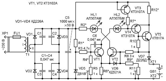
The power supply of the AZU from the network is carried out through a step-down transformer, which ensures electrical safety, followed by a rectifier bridge VD1 -VD4. If the AZU will be used to power the radio, then to eliminate the so-called multiplicative background, the diodes should be bridged with ceramic capacitors. Capacitor C1 smoothes the ripple of the rectified voltage, its capacitance should be at least 1000 μF for every 100 mA of current consumption. The reference voltage (9 V) is removed from the precision Zener diode VD5. Resistor R1 determines its rated stabilization current (10 mA). The voltage limitation on the battery (battery) upon reaching full charge is carried out by the differential cascade VT1VT2 as follows. The set voltage, at which it is necessary to limit the charging current, is determined by the voltage divider R2R3 and applied to the base of the transistor VT1, and the base VT2 receives voltage from the battery, taking into account the voltage drop across the diode VD7, which disconnects the battery from the battery when the voltage fails. Until the battery is charged, the voltage based on VT2 is less than that based on VT1, and therefore, VT2 is closed and the HL2 LED does not light. HL1 is on because VT1 is in active mode. The current value is determined by the resistance of the resistor R5 and the voltage based on VT1 and does not depend on the voltage on its collector. Such a circuit is known as a current source (IT) [2]. Consequently, the voltage drop across the resistor R4 will be stable, and HL1 will glow, indicating that the battery is charging. Its charging current is stable and does not depend on the voltage on the battery, since transistors VT3 and VT4 form IT.
Particular accuracy in maintaining the charging current is not required; limiting the battery voltage when reaching full charge is crucial. The accuracy of the differential stage and the parametric voltage regulator is quite enough to solve this problem. When the voltage on the battery corresponding to the full charge is reached, the transistor VT2 goes into active mode, its collector current appears, the HL2 LED lights up, indicating that the battery is charged, the current through VT1 will decrease, and the charge current will decrease to 0.01 ... 0.02Q, which eliminates battery recharging and damage. Capacitor C2 eliminates possible self-excitation, resistor R6 reduces the voltage across the VT2 collector, and therefore the power dissipated by it. The VD6 diode provides reliable closing of the VT4 transistor.
 The VT4 transistor can be replaced by any of the KT973, KT814, KT816 series and others (taking into account the charging current and the power dissipated in this case), VT3 - by any transistor from the KT3102, KT315, KT503 series, and VT1, VT2 - by any of the KT203, KT208, KT209 series KT502. The current transfer coefficient of the base of transistors is not less than 50.
If you need to charge the battery with large capacities and (or) voltages, you can assemble the battery according to the scheme shown in Fig. 2, using transistors of a different structure as more common. An exemplary voltage and a comparison with it is supplied to the base of the transistors of the differential stage through dividers or directly, depending on the voltage of the battery. So, if its voltage is less than 9 V (stabilization voltage D818 = 9 V), then the resistors R9, R11 are excluded, the voltage is supplied to the VT2 base through the resistor R8, and the required value of the battery charging end voltage is set by the divider R3R4R5.
 If the battery voltage is more than 9 V, then the resistors R4, R5 are excluded, and the charging end voltage is set by the divider R8R9R1 1. The current of the dividers is selected in the range of 0.5 ... 1 mA. The resistor R6 sets the charging current of about 10 mA after determining the voltage on the basis of the transistor VT1. By choosing a resistor R1, the nominal stabilization current of the Zener diode VD5 is set to 10 mA. The VD6 diode limits the reverse voltage at the VT2 emitter junction, which can occur during a short circuit in the battery circuit.
Transistors VT3, VT4, VT5 form a powerful current source [2]. Thanks to the first of them, the voltage drop across the resistors R7, R12 can be set on the order of 1 V, which may be required if the battery voltage is comparable with the voltage at the output of the rectifier. With a battery voltage of less than 9 V, the VT3 transistor can be excluded, and the voltage drop across the resistors R7, R12 should be selected equal to several volts, while the power dissipated by the transistor VT5 will decrease, but a resistor R12 with a correspondingly higher dissipation power will be required.
The power and voltage on the secondary winding of the step-down transformer T1, the electrical parameters of the diodes VD1-VD4, VD7, transistor VT5 are determined by the capacity and voltage of the battery. To ensure long trouble-free operation of the device, the limit values of the parameters of semiconductor devices and resistors must exceed the values existing in the device by 2 ... 3 times. If it is assumed that the device will work around the clock without supervision, special attention should be paid to fire safety. The transformer must be of sufficient power, with reliable insulation and low idle current, indicating the absence of saturation of the magnetic circuit and a sufficient number of turns of the primary winding. To determine the maximum permissible mains voltage and identify short-circuited turns it is useful to take off the magnetization characteristic of the transformer (the dependence of the open-circuit current on the voltage on the mains winding). A sharp increase in the open-circuit current is permissible only when the voltage on the winding exceeds the rated mains by 10% (with a nominal 230 V it is 253 V), which indicates a sufficient number of turns of the primary winding. The housing of the control unit must also meet the requirements of fire and electrical safety.
When setting up, the rectifier of the AZU should be loaded with a current of 0.01 ... 0.02 Q and the nominal charging current (approximately 10 mA) should be set by selecting resistor R6, since it is in this mode that the charging current should be limited. Then, depending on the voltage of the battery, select the configuration of the circuit of the device and pre-set the voltage limiting the charging of the battery. If this voltage is more than 9 V, then, according to the above, the base of the transistor VT1 is connected to the zener diode VD5 through the resistor R3, in this case the voltage on its emitter will be less than about 0.65 V, i.e. about 8.4 V. Therefore , at a current of about 10 mA, the nearest value of the resistor R6 is 820 Ohms. Then determine the values of the resistors R7, R12 and the need for a transistor VT3 to achieve the required charging current. When measuring the charging current, the HL1 LED should not light. To perform this work, the AZU is loaded with a chain according to the scheme in Fig. 3. Next, the tuning resistor R11 sets the current to 0.01 ... 0.2Q with a voltage at the output of the AZU corresponding to 1.5 V for each battery of the battery.
If the battery voltage is less than 9 V, then R9, R11 are excluded, using the dividers R3R4R5, the voltage corresponding to the charged battery plus the voltage drop across the VD7 diode is pre-set, then, according to the above, the resistance of the resistors R6, R7, R12 is determined and the charge limiting voltage is finally set Battery trimmer resistor R5.
Literature
A little bit about charging nickel-cadmium batteries. - Radio, 1996, No. 7, p. 48.
Semushin S. Sources of current and their application. - Radio, 1978, No. 1, p. 39; No. 2, p. 44.
Author: S. Tikhonov, the city of Kaltan, Kemerovo region