REPAIRING AND NOT THROWING AWAY

Richtige Fernseher haben Röhren!

Richtige Fernseher haben Röhren!

In Brief: On this site you will find pictures and technical information about Service Modes, Circuit Diagrams, Firmware Update procedure, Disassemble procedure, Universal remote control set-up codes, Troubleshooting and more....

If you go into the profession, you will obtain or have access to a variety of tech tips databases HERE IT IS Master Electronics Repair !.

These are an excellent investment where the saying: 'time-is-money' rules. However, to learn, you need to develop a general troubleshooting approach - a logical, methodical, method of narrowing down the problem. A tech tip database might suggest: 'Replace C536' for a particular symptom. This is good advice for a specific problem on one model. However, what you really want to understand is why C536 was the cause and how to pinpoint the culprit in general even if you don't have a service manual or schematic and your tech tip database doesn't have an entry for your sick TV or VCR.

While schematics are nice, you won't always have them or be able to justify the purchase for a one-of repair. Therefore, in many cases, some reverse engineering will be necessary. The time will be well spent since even if you don't see another instance of the same model in your entire lifetime, you will have learned something in the process that can be applied to other equipment problems.
As always, when you get stuck, checking out a tech-tips database may quickly identify your problem and solution.In that case, you can greatly simplify your troubleshooting or at least confirm a diagnosis before ordering parts.

Happy repairing!
Today, the West is headed for the abyss. For the ultimate fate of our disposable society is for that society itself to be disposed of. And this will happen sooner, rather than later.

How to use the site:

- If you landed here via any Search Engine, you will get what you searched for and you can search more using the search this blog feature provided by Google. You can visit more posts scrolling the left blog archive of all posts of the month/year,
or you can click on the main photo-page to start from the main page. Doing so it starts from the most recent post to the older post simple clicking on the Older Post button on the bottom of each page after reading , post after post.

You can even visit all posts, time to time, when reaching the bottom end of each page and click on the Older Post button.

- If you arrived here at the main page via bookmark you can visit all the site scrolling the left blog archive of all posts of the month/year pointing were you want , or more simple You can even visit all blog posts, from newer to older, clicking at the end of each bottom page on the Older Post button.
So you can see all the blog/site content surfing all pages in it.

- The search this blog feature provided by Google is a real search engine. If you're pointing particular things it will search IT for you; or you can place a brand name in the search query at your choice and visit all results page by page. It's useful since the content of the site is very large.

Note that if you don't find what you searched for, try it after a period of time; the site is a never ending job !

..............The bitterness of poor quality is remembered long after the sweetness of todays funny gadgets low price has faded from memory........ . . . . . .....
Don't forget the past, the end of the world is upon us! Pretty soon it will all turn to dust!

©2010, 2011, 2012, 2013, 2014 Frank Sharp - You do not have permission to copy photos and words from this blog, and any content may be never used it for auctions or commercial purposes, however feel free to post anything you see here with a courtesy link back, btw a link to the original post here , is mandatory.
All posts are presented here for informative, historical and educative purposes as applicable within fair use. NOTHING HERE IS FOR SALE !

Showing posts with label HARMAN_KARDON. Show all posts

Thursday, 1 October 2020

HARMAN KARDON CD91 ULTRAWIDEBAND LINEAR PHASE CASSETTE DECK CIRCUIT DIAGRAM, EXPLODED VIEW OF MECHANISM AND WIRING DIAGRAM


 Exploded views of CD mechanism, tape deck, full circuit diagram and wiring diagram.

Exploded view


Exploded view - tape deck


Full circuit diagram


Wiring diagram


 CD191 Harman Kardon Ultrawidband Linear Phase Cassette Deck schematic, exploded view of the deck mechanism
The deck mechanism exploded view


The Harman Kardon CD191 exploded view


Wiring diagram

Schematic full

Tuesday, 18 August 2020

HARMAN KARDON CA260 HIGH FIDELITY CAR AMPLIFIER IDLING CURRENT ADJUSTMENT, SCHEMATIC, WIRING DIAGRAM AND EXPLODED VIEW


Power Output, RMS
: 60 watts per channel into 4 Ohms, 20 ~ 20,000Hz
: 90 watts per channel into 2 Ohms, 20 ~ 20,000Hz
: 180 watts bridged mono into 4 Ohms, 20 ~ 20,000Hz
Alignment procedure: Idling current adjustment
Conditions:
-Connect the DC voltmeter between TPl and TP2 and between TP3 and TP4.
-Connect a 13. 8V power supply to the 12V Battery
Power In terminal.
-After the power on, wait for 5 minutes before measuring to be sure of the most stable operation.
Inspection:
-Confirm that the idling current is 50mA :t 20mA (voltage: 33mV:t 13mV).
If the current measured does not fall within the range specified , adjust it with the procedure below.
Adjustment
Note: When replacing or disconnecting a resistor, disconnect the power supply first.
After the adjustment is complete, let the unit settle down for 10 minutes, than double-check that the idling current is set properly.
Exploded view
Schematic diagram
Wiring diagram
Protection circuit
If the temperature inside the CA260 rises above 80 the protection circuit comes into operation , decreasing output. At this time the protect indicator blinks. If the temperature comes back below 80 C by natural cooling, output returns as it was.
If the temperature rises above 100 , the power supply circuit is shut off . Not only does the output stop, but also the protect indicator goes out. If this happens, it is possible that the CA260 is broken. However, even in this state, it cannot be always said that it is broken because the unit may operate when the temperature comes back below 80 C by natural cooling.

Wednesday, 15 January 2020

HARMAN KARDON DMC250 -230 DIGITAL MEDIA CENTER POWER SUPPLY CIRCUIT – ICE3B0365 - DVD PLAYER

Harman kardon DMC250 -DMC230 ICE3B0365 Off-Line SMPS Current Mode Controller
The CoolSET F3(Jitter version) meets the requirements for Off-Line Battery Adapters and low cost SMPS for the lower power range. By use of a BiCMOS technology a wide VCC range up to 26V is provided. This covers the changes in the auxiliary supply voltage if a CV/CC regulation is implemented on the secondary side. Furthermore an Active Burst Mode is integrated to fulfill the lowest Standby Power Requirements <100mW at no load and Vin = 270VAC. As during Active Burst Mode the controller is always active there is an immediate response on load jumps possible without any black out in the SMPS. In Active Burst Mode the ripple of the output voltage can be reduced <1%. Furthermore Auto Restart Mode is entered in case of Overtemperature, VCC Overvoltage, Output Open loop or Overload and VCC Undervoltage. By means of the internal precise peak current limitation, the dimension of the transformer and the secondary diode can be lowered which leads to more cost efficiency.
Features
# 650V Avalanche Rugged CoolMOS with built in switchable Startup Cell
# Active Burst Mode for lowest Standby Power
@ light load controlled by Feedback Signal
# Fast Load Jump Response in Active Burst Mode
# 67 kHz fixed Switching Frequency
# Auto Restart Mode for Over temperature Detection
# Auto Restart Mode for Overvoltage Detection
# Auto Restart Mode for Overload and Open Loop
# Auto Restart Mode for VCC Undervoltage
# User defined Soft Start
# Minimum of external Components required
# Max Duty Cycle 75%
# Overall Tolerance of Current Limiting < ±5%
# Internal Leading Edge Blanking
# BiCMOS technology provides wide VCC Range
# Frequency Jittering for Low EM
Pin configuration 

Pin
Symbol
Function
1
SoftS
Soft-Start
2
FB
Feedback
3


CS


Current Sense/
650V1) CoolMOS® Source
4
Drain
650V1) CoolMOS® Drain
5
Drain
650V1) CoolMOS® Drain
6
N.C.
Not Connected
7
VCC
Controller Supply Voltage
8
GND
Controller Ground
Pin Functionality
Soft (Soft Start, Auto Restart & Frequency Jittering Control)
The SoftS pin combines the function of Soft Start during Start Up and error detection for Auto Restart Mode. These functions are implemented and can be adjusted by means of an external capacitor at SoftS to ground. This capacitor also provides an adjustable blanking window for high load jumps, before the IC enters into Auto Restart Mode. Furthermore this pin is also used to control the period of frequency jittering during normal load.
FB (Feedback)
The information about the regulation is provided by the FB Pin to the internal Protection Unit and to the internal PWM-Comparator to control the duty cycle. The FBSignal controls in case of light load the Active Burst Mode of the controller.
CS (Current Sense)
The Current Sense pin senses the voltage developed on the series resistor inserted in the source of the integrated CoolMOS. If CS reaches the internal threshold of the Current Limit Comparator, the Driver output is immediately switched off. Furthermore the current information is provided for the PWMComparator to realize the Current Mode.
Drain (Drain of integrated CoolMOS)
Pin Drain is the connection to the Drain of the internal CoolMOS.
VCC (Power supply)
The VCC pin is the positive supply of the IC. The operating range is between 10.3V and 26V.
GND (Ground)
The GND pin is the ground of the controller.

Saturday, 14 December 2019

HARMAN KARDON CD91 CIRCUIT DIAGRAM AND EXPLODED VIEW WITH COMPONENT LIST. CASSETTE DECK MECHANISM EXPLODED VIEW

Ultrawideband Linear Phase Cassette Deck – Harman Kardon CD91 circuit diagram and exploded view with component list.
Cassette Deck mechanism exploded view
Exploded view
Schematic [circuit diagram]
Wiring diagram

Saturday, 6 April 2019

THE HARMAN KARDON – PM640 – AMPLIFIER – CIRCUIT DIAGRAM

The Harman Kardon – PM640 – amplifier – Circuit Diagram

 Hi-Current Capability Integrated Amplifier - Harman Kardon PM640 – Schematic
RMS Power Output > 35W
Power Supply > AC120V – 60Hz
Weight > 6.4kg
SCHEMATIC
PWB
CLICK ON THE PICTURES TO MAGNIFY

HARMAN/KARDON - DVD 26-28 – DVD 39-49 ANF DVD 50 – 50 FIVE DISC CHANGER – SMPS CIRCUIT DIAGRAM

harman/kardon - DVD 26-28 – DVD 39-49 anf DVD 50 – 50 Five disc changer – SMPS Circuit Diagram

Power Supply Schematic – harman/kardon – DVD50 5 Disc changer – DVD26-28 – DVD39-49 – Harman/kardon DVD players
DVD 26 - 28 SMPS SCHEMATIC
DVD 39 - 49 SMPS SCHEMATIC
DVD 50 - 5 disc changer
Click on the schematic to zoom in

HARMAN/KARDON DVD 50 – CIRCUIT DIAGRAM – DISASSEMBLY - 5 DISC DVD CHANGER

Harman/kardon DVD 50 – Circuit Diagram – Disassembly - 5 Disc DVD Changer


Applicable Discs: 5-inch (12cm) or 3-inch (8cm) DVD-Movie, CD, Video CD, MP3-CD, HDCD, CD-R or CD-RW discs.
Region 1 DVD-Movie discs
DVD: Single/Single Layer, Single Side/Dual Layer, Dual Side/Dual Layer
Linear PCM, Dolby Digital or DTS Audio
Video Signal System: NTSC
Composite Video Output: 1Vp-p/75 Ohms, sync, negative polarity
S-Video: Y/Liminace: 1Vp-p/75 Ohms, sync, negative polarity
C/Chrominance: 0.286Vp-p
Component Video Output: Y: 1Vp-p/75 Ohms, sync, negative polarity
Pr: 0.7Vp-p/75 Ohms
Pb: 0.7Vp-p/75 Ohms
Progressive Scan Output: Y: 1Vp-p/75 Ohms, sync, negative polarity
Pr: 0.7Vp-p/75 Ohms
Pb: 0.7Vp-p/75 Ohms
Analog Audio Output: HDCD: 2.0V RMS +/– 0.2V
Others: 1.0Vp-p RMS +/– 0.2V
Coaxial Digital Audio Output: 0.5Vp-p/75 Ohms
Frequency Response: 4Hz – 22kHz +/– 0.5dB (48kHz sampling)


AC Power: 100 – 240VAC 50/60Hz (Refer to back of the set.)
Power Consumption: 18 Watts
DISASSEMBLY
Tray Door
1.Eject the disc tray.
2.Lift up the tray door in the direction of the arrow.
Front Panel
1. Eject the disc tray. (See Fig. 2-2)
2. Remove the tray door. (See Fig. 2-2)
3. Pull the front panel toward you while pressing
5 stoppers to disengage, and remove the front panel.
CIRCUIT BOARD DISASSEMBLY
[Before removing the main circuit board, be sure to shortcircuit the laserdiode output land.  After replacing the main circuit board, open the land after inserting the flexible connector.]
Disassemble Main circuit board, Jack circuit board, Power circuit board and MD Ass'y DPM1.
1. Remove the top case. 
2. Remove 10 screws (B).
3. Disassemble Main circuit board and Jack circuit board from Bracket Main.
4. Unscrew 3 screws(C) at Bracket Main.
5. Disassemble Bracket Main from Main chassis.
6. Unscrew 4 screws(D) at MD Ass'y DPM1.
7. Turn the portion the direction of arrow to move the Base Assembly Tray in front of you.
8. Release the other 3 screws(E).
9. Disassemble MD Ass'y DPM1 from Main chassis.
10. Unscrew 4 screws(F) at Power circuit.
11. Disassemble power circuit board from Main chassis.
Digitron and Key Circuit Board
1. Remove the front panel. 
2. Release 5 screws (G), and remove the digitron circuit board.
Exploded view
DVD DSP SCHEMATIC
DRIVE AND RF SCHEMATIC
PANTERA SCHEMATIC
MEMORY SCHEMATIC
TIMER AND KEY SCHEMATIC
AV SCHEMATIC
AV JACK SCHEMATIC

Friday, 5 April 2019

HARMAN KARDON - HK-3370 _ HK-3470 - STEREO AMPLIFIER - POWER AMP-SCHEMATIC]

HARMAN KARDON - HK-3370 _ HK-3470 - Stereo Amplifier - POWER AMP-SCHEMATIC]


POWER AMPLIFIER & PRE-AMPLIFIER _ SCHEMATIC
CLICK ON THE Pictures TO ZOOM IN

Wednesday, 3 April 2019

HARMAN KARDON HT32 - HT40 - HT46 - LCD TV - POWER SUPPLY VOLTAGES

HARMAN KARDON HT32 - HT40 - HT46 - LCD TV - POWER SUPPLY VOLTAGES


SMPS BOARD
VOLTAGE CHART

Tuesday, 2 April 2019

HARMAN KARDON - MAS101-MAS102-MAS111 - SCHEMATIC (IRF14212H-117P_FSFR2100)

HARMAN KARDON - MAS101-MAS102-MAS111 - SCHEMATIC (IRF14212H-117P_FSFR2100)


SPECIFICATIONS
System
Power output 65 watts per channel, 20hz – 20khz, thd<0.07%, into 6 ohms, both channels driven
Bandwidth 20hz – 35khz, –3dB
System frequency response 20hz – 20khz, ±0.5dB
Signal-to-noise ratio, a-weighted 90dB (analog inputs), 96dB (digital inputs) channel separation ≥65dB crosstalk between sources ≥70dB
Line-level input sensitivity at 1khz 250mV rMS, ±1dB
Phono MM input sensitivity at 1khz 7.5mV
Loudspeakers
Low-frequency transducers two 130mm honeycomb composite drivers, ported high-frequency transducers two 25mm MMd domes, shielded nominal impedance 8 ohms
Sensitivity (2.83V/1m) 85dB
frequency response 60hz – 25khz (–3dB) crossover frequency 2200hz
FM Tuner Section frequency range 87 – 108.0Mhz usable sensitivity Ihf1.3µV/13.2dBf frequency response 10hz to 15.3khz Signal-to-noise ratio mono/stereo 68/65dB distortion mono/stereo 0.15/0.3%
Stereo separation 35dB @ 1khz, 100% deviation @ 65dBf
Selectivity ±300khz; 65dBf
Image rejection 80dB. Ifrejection 90dB tuner output level 1khz, ±50khz, dev 500mV number of presets 30 rdS capability PS (program service), rt(dynamic radio text)
AMP SCHEMATIC  (Click on the Schematics to Zoom In)
SMPS SCHEMATIC

Monday, 1 April 2019

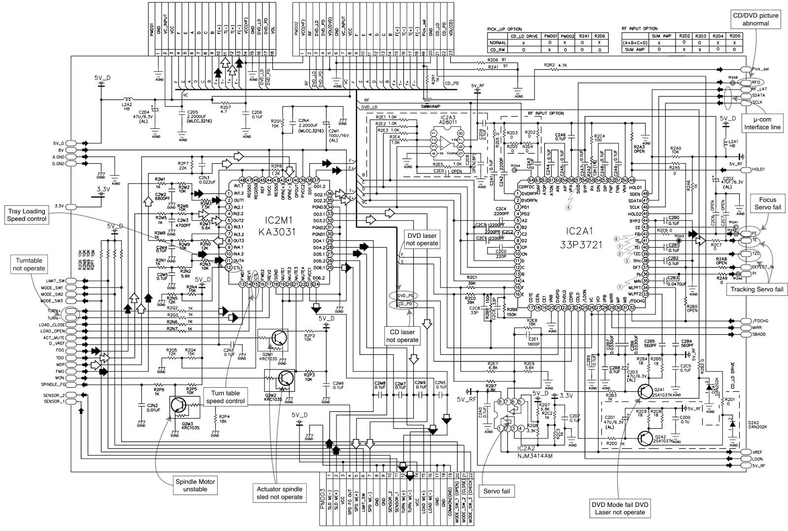
HARMAN / KARDON DVD 25 - SMPS SCHEMATIC [CIRCUIT DIAGRAM] (NDV8501 - NDV8601)

harman / kardon DVD 25 - SMPS SCHEMATIC [Circuit Diagram] (NDV8501 - NDV8601)


harman/kardon NDV8501 / NDV8601 Based Progressive Scan DVD Player
Model Number: DVD25

Compactable with CD as well as DVD with Region Code ‘0’ or ‘2’
SMPS SCHEMATIC [Click on the pictures to Zoom In]
To reset the unit
* Set the unit in SY-BY.
* Push “Clear” button on the remote control, until the unit Power ON. [This will not change the Zone]
To read the software version.
* Set the unit in ON mode.
* Push Set-up button on the remote control.
* Push ‘1211’, and then a new menu showing the data of the unit.
To Exit, push Set-up.