REPAIRING AND NOT THROWING AWAY

Richtige Fernseher haben Röhren!

Richtige Fernseher haben Röhren!

In Brief: On this site you will find pictures and technical information about Service Modes, Circuit Diagrams, Firmware Update procedure, Disassemble procedure, Universal remote control set-up codes, Troubleshooting and more....

If you go into the profession, you will obtain or have access to a variety of tech tips databases HERE IT IS Master Electronics Repair !.

These are an excellent investment where the saying: 'time-is-money' rules. However, to learn, you need to develop a general troubleshooting approach - a logical, methodical, method of narrowing down the problem. A tech tip database might suggest: 'Replace C536' for a particular symptom. This is good advice for a specific problem on one model. However, what you really want to understand is why C536 was the cause and how to pinpoint the culprit in general even if you don't have a service manual or schematic and your tech tip database doesn't have an entry for your sick TV or VCR.

While schematics are nice, you won't always have them or be able to justify the purchase for a one-of repair. Therefore, in many cases, some reverse engineering will be necessary. The time will be well spent since even if you don't see another instance of the same model in your entire lifetime, you will have learned something in the process that can be applied to other equipment problems.
As always, when you get stuck, checking out a tech-tips database may quickly identify your problem and solution.In that case, you can greatly simplify your troubleshooting or at least confirm a diagnosis before ordering parts.

Happy repairing!
Today, the West is headed for the abyss. For the ultimate fate of our disposable society is for that society itself to be disposed of. And this will happen sooner, rather than later.

How to use the site:

- If you landed here via any Search Engine, you will get what you searched for and you can search more using the search this blog feature provided by Google. You can visit more posts scrolling the left blog archive of all posts of the month/year,
or you can click on the main photo-page to start from the main page. Doing so it starts from the most recent post to the older post simple clicking on the Older Post button on the bottom of each page after reading , post after post.

You can even visit all posts, time to time, when reaching the bottom end of each page and click on the Older Post button.

- If you arrived here at the main page via bookmark you can visit all the site scrolling the left blog archive of all posts of the month/year pointing were you want , or more simple You can even visit all blog posts, from newer to older, clicking at the end of each bottom page on the Older Post button.
So you can see all the blog/site content surfing all pages in it.

- The search this blog feature provided by Google is a real search engine. If you're pointing particular things it will search IT for you; or you can place a brand name in the search query at your choice and visit all results page by page. It's useful since the content of the site is very large.

Note that if you don't find what you searched for, try it after a period of time; the site is a never ending job !

..............The bitterness of poor quality is remembered long after the sweetness of todays funny gadgets low price has faded from memory........ . . . . . .....
Don't forget the past, the end of the world is upon us! Pretty soon it will all turn to dust!

©2010, 2011, 2012, 2013, 2014 Frank Sharp - You do not have permission to copy photos and words from this blog, and any content may be never used it for auctions or commercial purposes, however feel free to post anything you see here with a courtesy link back, btw a link to the original post here , is mandatory.
All posts are presented here for informative, historical and educative purposes as applicable within fair use. NOTHING HERE IS FOR SALE !

Showing posts with label RADIO. Show all posts

Tuesday, 8 September 2020

NATIONAL PANASONIC RQ 432S SCHEMATIC DIAGRAM , LAYOUT AND DIAL CORD SETTING


Vintage Cassette Radio Recorder – National Panasonic RQ 432S schematic, layout and dial cord setting.


The main fault that can occur to this set is the tuning drift as climatic change.  The inductance of TR54 and or TR56 changes.  Replace them if this type of fault occurs. 

At the amplifier stage, C19 and C20 [capacitors connected between collector base of the output transistors] may get leak.  Resulting distorted audio output.  They have used steroflex capacitors there.  I’ve replaced both of them with disc ceramic [250VDC] type, and going fine.

The C34 [1000MFD-10V] should be checked for its capacitance.  It is best to replace it.  Sound distortion can occur if this capacitor is damaged.

C32 [220MFD 10V] can also be problematic.  Replace it.

I own this model set, which bought at mid of 70s, I presume, is working fine till time.  There is no more problems can occur to this set.  

Amplifier section schematic

Tuner section schematic
PCB layout
Dial chord setting

Saturday, 2 May 2020

AIWA CS 880E 3 BAND STEREO RADIO CASETTE RECORDER SCHEMATIC DIAGRAM - DESCRIPTION OF THE MD-3 MECHANISM – EXPLODED VIEW


Aiwa CS 880E Schematic diagram, 3 band stereo radio cassette recorder– exploded view – Vintage set

Description of the MD-3 mechanism

With the plate button pressed, the trigger lever (PLAY ) moves in the direction of the arrow <- (1), the gear (PLAY ) is released from the boss of the trigger lever (PLAY ) engages with the gear flywheel and rotates in the direction of the arrow <- (2), the boss (A) of the gear (PLAY ) touches the trigger lever (PLAY ) and the gear stops rotating.

When the gear (PLAY ) rotates, the lever (PLAY ) moves in the direction of the arrow <- (3) along the cam groove on the rear of the gear to push up the operation chassis in the direction of the arrow «- (4).  The PLAY button which has been locked is released by pressing the STOP button, the trigger lever (PLAY ) moves in the direction of the arrow *- (5), the boss (A) of the gear (PLAY ) is released and the PLAY operation stops.


Description of the FF Operation
When the FF button is pressed, the trigger lever FF moves in the direction of the arrow (1), the boss of the gear FR cam is released and engages with the gear wheel to rotate in the direction of the arrow. <- (2), the boss (A ) touches the boss of the trigger lever FF and the gear FR cam stops. The FR lever B moves in the direction of the arrow «- (3) along the groove of the gear FR cam, the FR lever B moves in the direction of the arrow <- (3), the FR lever C compresses the gear of the FR lever Ass'y against the Take-up
reel disc ass'y to perform the FF operation.


REW Operation
When the REW button is pressed, the trigger lever REW moves in the direction of the arrow <- (1) and pushes the lever REW in the direction of the arrow <- (2). The trigger lever FF releases the boss A of the gear at that time, the gear FR engages with the gear flywheel, rotates in the direction of the arrow <- (3), boss B touches the trigger lever FF and rotation stops.  The FR gear B is moved in the direction the arrow «- (4) by means of the cam of the gear FR following the rotation of the gear FR , pulls the FR lever C in the direction of the arrow «- (5) and moves the FR lever ass'y in the direction of the arrow <- (6) to rotate the Take-up reel disc reel disc ass'y to perform the R E W operation.


Description of the PAUSE Operation
When the PAUSE button is pressed, the trigger lever PAUSE moves in the direction o f the arrow *- (1), the boss A of the gear PA U SE is released, engages with the gear flywheel and rotates in the direction of the arrow <- (2), the boss B touches the trigger PAUSE and rotation stops.  The PAUSE lever moves in the direction of the arrow •*- (3) along the cam groove of the PAUSE gear at that time. The PLAY idler lever and the pinch lever ass'y is moved to perform the PAUSE operation at that time.
When the PAUSE button is pressed again, the button is released from locking and simultaneously the boss B of the gear PAUSE is released from the trigger lever PAUSE and the PAUSE operation is released.


REC Operation
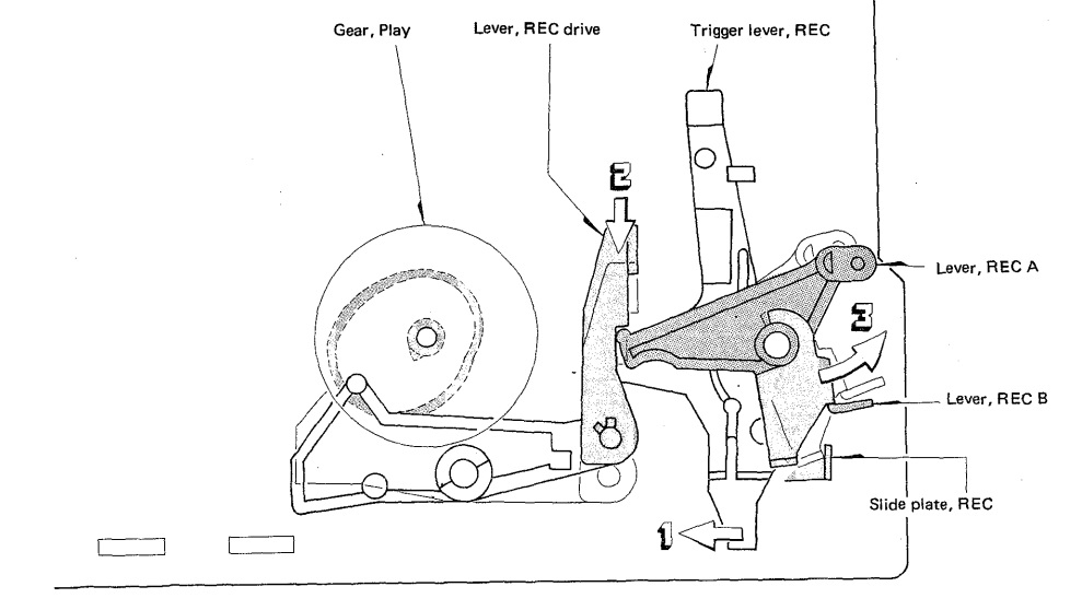
When the REC and PLAY buttons are pressed simultaneously, the trigger lever REC moves in the direction of the arrow +- (1 ).  The PLAY operation is performed simultaneously at that time, so the REC lever driver moves in the direction of the arrow «- (2),
pushes the lever RECA, B in the direction of the arrow <- (3), the interlocked slide REC plate pulls the rod, the slide switch is operated and the unit enters the R E C mode.  When one of the STOP, FF and REW buttons is pressed, the REC trigger lever is released from the REC lever driver and only the REC operation is released.


Description of the Auto-stop Operation
The motor rotation is transmitted to the gear auto-kick of the MD-3 mechanism via the slip pulley FR ass'y.  The slip disk presses the lever auto A in the direction of the arrow <- (1) when the Take-up reel disc ass'y is rotating, so the boss of the lever auto A moves along the cam (A) groove of the gear auto-kick.  When the reel discs (S, T sides) stop, the lever auto A stops in the condition being moves in the direction of the arrow (2).  The cam (B) of the gear auto-kick moves the lever auto A in the direction of the arrow «- (3), operates the plate auto-kick in the direction of the arrow «- (4) to release the plate lock and performs the AUTO STOP operation.


Spring application position


Exploded view


Schematic diagram


Sunday, 5 April 2020

TOSHIBA RT 6015 STEREO RADIO CASETTE RECORDER - DIAL CORD RESTRINGING - WIRING DIAGRAM – SCHEMATICS OF MECHANISM AND CABINET EXPLODED VIEW

 Used ICs: TA7358AP, TA7343P, TA7757P, TA7233P, TA7668BP, TA7233P, TA7343P

Dial cord restringing

Tight up the dial cord for the designated length, and cement after two ties.

Hook the dial cord to the spring and pass through the opening of the drum from the inside.

Turn the variable capacitor fully clockwise and mount the drum onto it.

[to prevent the variable capacitor from damage, slightly return it in the opposite direction and fasten the dial cord.]

Wind the dial cord in numerical order as illustrate.

Turn the variable capacitor fully counterclockwise and set the pointer to the “0” position in the dial scale.


Wiring diagram

Schematic

Mechanism exploded view


Cabinet exploded view

Saturday, 6 April 2019

BRITANIA BS-72 – CD-PLAYER – RADIO - CASSETTE COMBO - SCHEMATIC

BS-72CD-PLAYER – RADIO - CASSETTE COMBO - BRITANIA  - Circuit Diagram _ Exploded view
Used ICs: TA2157F – TC94A29F/FA – MM1469 – TA2132P / SA2132 – TA7343 – KT2206B / KA2206B – LM8560 – A2282 – KA9258D / MM1469XF

SCHEMATICS
EXPLODED VIEW
CLICK ON THE PICTURES TO MAGNIFY

RCA VALVE RADIO CIRCUIT DIAGRAM - 1960 MODEL TRANSFORMER-LESS TYPE

RCA Valve Radio Circuit Diagram - 1960 model Transformer-less type

1960 Model Transformer-less [Barterer Type] Radio - RCA Victor - Schematic
Circuit Diagram

PHILIPS AZ3830/55 MP3 CD SOUNDMACHINE – CIRCUIT DIAGRAM

PHILIPS AZ3830/55 MP3 CD Soundmachine – Circuit Diagram

TDA8944J – PT2314  
Power amplifier schematic and PWB
Keyboard
LCD board
WMA & Memory
Click on the schematics to zoom in

PHILIPS SATURN 563 – VACUUM TUBE RADIO SCHEMATIC

Philips Saturn 563 – Vacuum Tube Radio Schematic

Used Valves (Tubes): ECH81 - EF89 - EBF89 - EABC80 - EM80 - EL86 - EZ81
Schematic

PHILIPS BR 405A - AC-DC RADIO - CIRCUIT DIAGRAM

Philips BR 405A - AC-DC Radio - Circuit Diagram

Vacuum tubes used: ECH42 – EAF42 – EBC41 – EL42 – EM34 – AZ41
My age was 1-year; when this set was released by Philips in 1951.  Now I'm 67.
Circuit Diagram

PHILIPS FR 680A STEREO RADIOGRAM – CIRCUIT DIAGRAM

Philips FR 680A Stereo Radiogram – Circuit Diagram

Tubes used: EL84 – ECC83 – ECH81 - EAA91 – EF184 – EF93 – EM80
Circuit Diagram

PHILIPS AL695 – FM-AM RADIO – SCHEMATIC

Philips AL695 – FM-AM radio – Schematic

AM-FM Radio – Philips – Circuit diagram – Wiring diagram
Circuit diagram and PWB

PHILIPS AZ1010 – CD RADIO CASSETTE RECORDER – CIRCUIT DIAGRAM

Philips AZ1010 – CD Radio Cassette Recorder – Circuit Diagram

Tuner board
Combi board
Click on the schematics to zoom in