 HOW TO MAKE ADJUSTMENTS AKAI CT 1417 UK AND CIRCUIT DIAGRAM

AKAI CT 1417 UK
CRT TV
ADJUSTMENTS AND CIRCUIT DIAGRAM
Electrical Adjustments
TEST EQUIPMENT
1. VIF Sweep Generator
2. SIF Sweep Generator
3. DC Power Supply (14V)
4. Oscilloscope
5. Digital Multi Meter
6. CRT Colour Analyzer
7. Demagentizing Coil
8. Philips Pattern Generator
9. Frequency Counter
1. VIF Sweep Generator
2. SIF Sweep Generator
3. DC Power Supply (14V)
4. Oscilloscope
5. Digital Multi Meter
6. CRT Colour Analyzer
7. Demagentizing Coil
8. Philips Pattern Generator
9. Frequency Counter
TANK COIL ALIGNMENT
A. PREPARATION STEP
1. Connect OUTPUT lead of VIE Sweep Generator between SA101 Pin 4 and ground.
2. Connect lead of FROM DET between TP106 (Pin 19 of IC101) and ground.
3. Apply a +14V DC to lead of D408.
4. Apply a AGC bias (approx 6.14V) to TP104. Slowly adjust the AGC bias voltage until the waveform is just before saturation

ALIGNMENT STEP (SEE FIG)
1. Adjust T105 (TANK COIL) to obtain maximum amplitude
of response at 39.5MHz as in Fig.

VIF ALIGNMENT (TUNER VIF COIL)
A. PREPARATION STEP (SEE FIG)
1. Connect the output of VIF Sweep Generator between tuner test point TP and tuner case with input level of 54dBpV.
2. Connect resistor (100 Ohm) between TP101 and TP102.
3. Connect the vertical input of the Oscilloscope to the TP106 and ground.
4. Apply a +14V DC to lead of D408.
5. Apply a AGC bias (approx 6.14V) to TP104.
B. ALIGNMENT
1. Adjust AGC bias voltage slowly until the waveform is just before saturation.
2. Adjust the vertical gain control of the Oscilloscope until the waveform is 10 division on the screen.
3. Adjust the ferrete core in the tuner until the marker 39.5MHz has maximum amplitude and 35.07MHz has a difference of 1 division as shown in Fig.

AFC ALIGNMENT
A. PREPARATION STEP (SEE FIG)
1. Connect the signal output of Sweep/Marker Generator to TUNER IF OUTPUT with a signal level of 75dBpV.
2. Connect the vertical input terminal of Oscilloscope to TP107.
3. Apply a +14V DC to lead of D408.
4. Apply a +6.14V DC to TP104.
A. PREPARATION STEP (SEE FIG)
1. Connect the signal output of Sweep/Marker Generator to TUNER IF OUTPUT with a signal level of 75dBpV.
2. Connect the vertical input terminal of Oscilloscope to TP107.
3. Apply a +14V DC to lead of D408.
4. Apply a +6.14V DC to TP104.

ALIGNMENT STEP
1. Adjust the AGC bias voltage slowly until bottom portion of the waveform is just before saturation.
3. Adjust T106 (AFC COIL) for a waveform as shown in Fig.
1. Adjust the AGC bias voltage slowly until bottom portion of the waveform is just before saturation.
3. Adjust T106 (AFC COIL) for a waveform as shown in Fig.

SIF ALIGNMENT
A. PREPARATION STEP (SEE FIG)
1. Connect the output of SIF Sweep Generator between TP106 and ground.
2. Connect the vertical input of Oscilloscope between TP105 and ground.
3. Supply DC +14V to (+) lead of D408.
A. PREPARATION STEP (SEE FIG)
1. Connect the output of SIF Sweep Generator between TP106 and ground.
2. Connect the vertical input of Oscilloscope between TP105 and ground.
3. Supply DC +14V to (+) lead of D408.

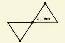
ALIGNMENT STEP
1. Adjust the output of Sweep Generator until a similar waveform is obtained (Fig).
2. Adjust T104 to obtain the marker 6.0MHz rested on the horizontal line (Fig).
NOTE: Input Level = 90dB.
1. Adjust the output of Sweep Generator until a similar waveform is obtained (Fig).
2. Adjust T104 to obtain the marker 6.0MHz rested on the horizontal line (Fig).
NOTE: Input Level = 90dB.
B+ ADJUSTMENT
1. Connect the digital voltmeter to TP401.
2. Adjust semi-fixed resistor VR901 until meter reading DC 112.25V ± 0.25V.
1. Connect the digital voltmeter to TP401.
2. Adjust semi-fixed resistor VR901 until meter reading DC 112.25V ± 0.25V.
HORIZONTAL CIRCUIT ADJUSTMENT
1. Connect the frequency counter to the heater of the CRT and ground.
2. Set the TV set to AV mode without any input signal.
3. Adjust the VR303 until the frequency is 15.625KHz ± 20Hz.
4. Set the TV set to TV mode and Receive Monoscope Pattern.
5. Adjust VR302 to move the pattern horizontally for center position.
VERTICAL CIRCUIT ADJUSTMENT
1. Connect the frequency counter between Vdeflection yoke and ground..
2. Set the TV to AV mode without any input signal.
3. Adjust the V-hold VR304 until the counter reads 44Hz ± 1 Hz
4. Set the TV set to TV mode and Receive Monoscope Pattern.
5. Adjust V-SIZE (VR401) control to obtain a normal picture.
FOCUS ADJUSTMENT
1. Set Contrast control to maximum position and Brightness control to middle position.
2. Adjust Focus control (on the FBT) to obtain a sharpest picture on the CRT.
1. Set Contrast control to maximum position and Brightness control to middle position.
2. Adjust Focus control (on the FBT) to obtain a sharpest picture on the CRT.
WHITE BALANCE ADJUSTMENT
1. Receive a Monoscope Pattern picture signal.
2. Turn the red, green and blue LOW LIGHT (VR501, VR502, VR503) controls to middle
position and turn the DRIVE (VR504, VR505) control to middle position.
3. Turn the Screen control on the FBT to minimum position.
4. Set the Sub-Brightness (VR305) control to middle position, then set the Contrast control
and Colour control to minimum position.
5. CN403 (Pin 1,2) with Join together.
6. Connect volt meter between (R508) and ground, and adjust Brightness control to the reading of DC 138V (±2V). If DC 138V cannot be obtain, adjust the Sub-Brightness control
(VR305).
7. Slowly turn the Screen control clockwise to the point where a horizontal line just illuminates.
8. Adjust VR501 to get a red horizontal line on CRT.
9. Adjust VR502 to get a yellow horizontal line on CRT.
10.Adjust VR503 to get a white horizontal line on CRT.
11.Reset the Service Switch (S401) to “NORMAL” position and turn Brightness control to middle position.
12.Adjust Drive (VR504, VR505) control to obtain a uniform white picture.
CIRCUIT DIAGRAM

REMOTE CONTROL CIRCUIT

CLICK ON THE IMAGE TO ZOOM IN