HP ENVY 17 – Disassembling procedure – How to remove the key board - How to remove the memory – How to remove the primary and secondary HDD – How to remove the top cover – Lapto repair and service

Category: Laptop Repair and Service
Contents of this article
- How to remove the top cover
- How to remove the HDD
- How to remove the key board
HP ENVY 17
DISASSEMBLING PROCEDURE
How to remove Computer feet
The computer feet are adhesive-backed rubber pads. The feet are included in the Rubber Feet Kit, spare part number 603798-001. There are 5 rubber feet that attach to the base enclosure in the locations illustrated below.
The computer feet are adhesive-backed rubber pads. The feet are included in the Rubber Feet Kit, spare part number 603798-001. There are 5 rubber feet that attach to the base enclosure in the locations illustrated below.

How to remove Battery
Before disassembling the computer, follow these steps:
1. Shut down the computer. If you are unsure whether the computer is off
or in Hibernation, turn the computer on, and then shut it down through the
operating system.
2. Disconnect all external devices connected to the computer.
3. Disconnect the power from the computer by first unplugging the power cord from the AC outlet and then unplugging the AC adapter from the computer.
Remove the battery:
1. Turn the computer upside down on a flat surface, with the front toward you.
2. Slide the battery release latch (1) to release the battery.
3. Pivot the front edge of the battery (2) upward

4. Remove the battery from the
computer.
To insert the battery, insert the rear edge of the battery into the battery
bay, and pivot the front edge of the battery downward until it is seated. The
battery release latch automatically locks the battery into place.
How to remove Primary hard drive
Before removing the primary hard drive, follow these
steps:
1. Shut down the computer. If you are unsure whether the computer is off
or in Hibernation, turn the computer on, and then shut it down through the
operating system.
2. Disconnect all external devices connected to the computer.
3. Disconnect the power from the computer by first unplugging the power cord from the AC outlet and then unplugging the AC adapter from the computer.
4. Remove the battery
5. Remove the memory module compartment cover
6. Remove the hard drive cover
Remove the primary hard drive:
1. Loosen the two captive Phillips screws that secure the hard drive cover to the computer.

2. Pivot the front edge of the
hard drive cover upward.

3. Remove the hard drive cover.
The hard drive cover is included in the Plastics Kit, spare part number
603795-001.
4. Disconnect the primary hard drive cable from the system board.

5. Use the Mylar tabs to remove
the primary hard drive from the computer

6. If it is necessary to
replace the primary hard drive bracket, remove the four Phillips PM3.0×3.0 screws
(1) that secure the bracket to the primary hard drive.
7. Lift the primary hard drive
bracket straight up (2) and remove the bracket from the hard drive.

8. If it is necessary to
replace the primary hard drive isolators, disconnect the isolators from the
hard drive bracket. The primary hard drive bracket and isolators are included
in the Hard Drive Hardware Kit, spare part number 603772-001.

How to remove RTC battery
Before removing the RTC battery, follow these steps:
1. Shut down the computer. If you are unsure whether the computer is off or in Hibernation, turn the computer on, and then shut it down through the operating system.
2. Disconnect all external devices connected to the computer.
3. Disconnect the power from the computer by first unplugging the power cord from the AC outlet and then unplugging the AC adapter from the computer.
4. Remove the battery
5. Remove the hard drive cover
Remove the RTC battery:
Remove the RTC battery from the socket on the system board.

How to remove Memory module
Before removing a memory module, follow these steps:
1. Shut down the computer. If you are unsure whether the computer is off or in Hibernation, turn the computer on, and then shut it down through the operating system.
2. Disconnect all external devices connected to the computer.
3. Disconnect the power from the computer by first unplugging the power cord from the AC outlet and then unplugging the AC adapter from the computer.
4. Remove the battery
5. Remove the hard drive cover
Remove the memory module:
1. Loosen the two captive Phillips screws (1) that secure the memory module compartment cover to the computer.
2. Pivot the front edge of the memory module compartment cover (2) up

3. Remove the memory module
compartment cover. The memory module compartment cover is included in the
Plastics Kit, spare part number 603795-001.
4. Spread the retaining tabs (1)
on each side of the memory module slot to release the memory module. (The
memory module tilts up.)
5. Remove the memory module (2)
by pulling it away from the slot at an angle

How to remove Secondary hard drive
Before removing the secondary hard drive, follow these
steps:
1. Shut down the computer. If you are unsure whether the computer is off or in Hibernation, turn the computer on, and then shut it down through the operating system.
2. Disconnect all external devices connected to the computer.
3. Disconnect the power from the computer by first unplugging the power cord from the AC outlet and then unplugging the AC adapter from the computer.
4. Remove the battery
5. Remove the hard drive cover
6. Remove the memory module compartment cover
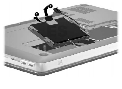
Remove the secondary hard drive:
1. Disconnect the secondary hard drive cable from the system board, and then release the cable from the clips and routing channel built into the base enclosure.
1. Disconnect the secondary hard drive cable from the system board, and then release the cable from the clips and routing channel built into the base enclosure.

2. Remove the four Phillips
PM2.5×6.0 screws that secure the secondary hard drive to the computer.

3. Use the Mylar tab (1) to
lift the rear edge of the secondary hard drive until it rests at an angle.
4. Remove the secondary hard
drive (2) by sliding it up and away from the computer at an angle.
How to remove WLAN module
Before removing the WLAN module, follow these steps:
1. Shut down the computer. If you are unsure whether the computer is off or in Hibernation, turn the computer on, and then shut it down through the operating system.
2. Disconnect all external devices connected to the computer.
3. Disconnect the power from the computer by first unplugging the power cord from the AC outlet and then unplugging the AC adapter from the computer.
4. Remove the battery
5. Remove the memory module compartment cover
Remove the WLAN module:
1. Disconnect the WLAN antenna cables (1) from the terminals on the WLAN module.
1. Disconnect the WLAN antenna cables (1) from the terminals on the WLAN module.
2. Remove the two Phillips
PM2.0×4.0 screws (2) that secure the WLAN module to the system board.
(The WLAN module tilts up.)
3. Remove the WLAN module (3) by pulling the module away from the slot at an angle
3. Remove the WLAN module (3) by pulling the module away from the slot at an angle

How to remove Keyboard
Before removing the keyboard, follow these steps:
1. Shut down the computer. If you are unsure whether the computer is off or in Hibernation, turn the computer on, and then shut it down through the operating system.
2. Disconnect all external devices connected to the computer.
3. Disconnect the power from the computer by first unplugging the power cord from the AC outlet and then unplugging the AC adapter from the computer.
4. Remove the battery
5. Remove the memory module compartment cover
Remove the keyboard:
1. Remove the three Phillips PM 2.5×5.0 screws (1) and the Phillips PM 2.5×7.0 (2) screw that secure the keyboard to the computer.
1. Remove the three Phillips PM 2.5×5.0 screws (1) and the Phillips PM 2.5×7.0 (2) screw that secure the keyboard to the computer.

2. Lift the rear edge of the
keyboard (1) until it rests at an angle.
3. Slide the keyboard (2) toward the display until the tabs on
the front edge of keyboard disengage from the slots in the top cover.

4. Release the zero insertion
force (ZIF) connector (1) to which the keyboard cable is attached, and then
disconnect the keyboard cable (2) from the system board.
5. Release the ZIF connector (3)
to which the keyboard light cable is attached, and then disconnect the
keyboard light cable (2) from the system board.

6. Remove the keyboard.
How to remove Top cover
Before removing the top cover, follow these steps:
1. Shut down the computer. If you are unsure whether the computer is off or in Hibernation, turn the computer on, and then shut it down through the operating system.
2. Disconnect all external devices connected to the computer.
3. Disconnect the power from the computer by first unplugging the power cord from the AC outlet and then unplugging the AC adapter from the computer.
4. Remove the battery
5. Remove the memory module compartment
6. Remove the keyboard
Remove the top cover:
1. Turn the computer upside down, with the front toward you.
2. Remove the four rubber feet (1) from the base enclosure. The rubber feet are included in the Rubber Feet Kit, spare part number 603798-001.
3. Remove the eight Phillips
PM2.5×8.0 screws (2) that secure the top cover to the computer.
4. Remove the three Phillips PM2.5×5.0 screws (3) that secure the top cover to the computer in the battery bay.
4. Remove the three Phillips PM2.5×5.0 screws (3) that secure the top cover to the computer in the battery bay.

5. Turn the computer
display-side up, with the front toward you.
6. Open the computer as far as it will open.
7. Release the ZIF connector (1) to which the power button board cable is attached, and then disconnect the power button board cable from the system board.
8. Release the ZIF connector (2) to which the TouchPad cable is attached, and then disconnect the TouchPad cable from the system board.
9. Remove the two Phillips PM2.5×5.0 screws (3) that secure the top cover to computer.

10. Lift the rear edge of the
top cover (1) until it rests at an angle.
11. Remove the top cover (2).
