 PANASONIC TC-P50G10 LED BLINKING CODE SERVICE MODE AND POWER SUPPLY CIRCUIT

PANASONIC TC-P50G10
LED BLINKING CODE SERVICE MODE AND POWER SUPPLY CIRCUIT
LED ON THE FROND OF THE TV
BLINKING
WHAT ITS MEAN BY BLINKING
WHAT ITS MEAN BY BLINKING
When there is any fault in the TV,its protection circuit detects
it and reset the TV and it will go to standby mode. At this time the power led
will blink showing which part of the unit is faulty.
And
you can identify the part by counting how many times the led blinks.
LED BLINKING CODE TABLE

Service Mode
How to enter into Service Mode
While pressing and holding VOLUME ( - ) button of the TV, press INFO button on the remote control three times .Do it with in Within 2 seconds.
While pressing and holding VOLUME ( - ) button of the TV, press INFO button on the remote control three times .Do it with in Within 2 seconds.
Using the key for different commands
Key 1 on the remote is used as Main Selection in forward directionKey 2 on the remote is used as Main Selection in reverse directionKey 3 on the remote is used as Sub Selection in forward directionKey 4 on the remote is used as Sub Selection in reverse direction
VOL key on the remote is used as to change the Value of sub items to increase or decrees
How to exit from service mode
Power off the unit using the remote or using the key on the frond panel.
Power off the unit using the remote or using the key on the frond panel.
How to enter to service tool mode
How to enter in to service tool
1. USE SRV-TOOL in Service menu .
2. Press ENTER (OK) key on the remote control.
1. USE SRV-TOOL in Service menu .
2. Press ENTER (OK) key on the remote control.
About SOS History
History of SOS LED flashing indication.
Staring form From left side; Last SOS, before Last, three occurrence before, 2nd occurrence after shipment, 1st occurrence after shipment.
This notifies, except 2nd and 1st occurrence after shipment will be cleared by Self-check indication and forced to factory shipment setting.
ABOUT POWER ON TIME or COUNT
Note : To view TIME or COUNT display , highlight position, then press MUTE for 3sec.
Time : Cumulative power on time, indicated hour : minute by decimal
Count : Number of ON times in decimal
Note : This indication will not be cleared by self-checks or any other command.
Exit
1. Disconnect the AC cord from wall outlet.
Hotel mode of the TV
1. Usage
To restrict unauthorized menu stetting
2. To access to hotel mode of the do the flowing with in 2 seconds .
Press TV : and then together Vol. Down and Vol. Down on REMOTE the press INPUT. Do the same 3 times to enter in to hotel mode
1. Usage
To restrict unauthorized menu stetting
2. To access to hotel mode of the do the flowing with in 2 seconds .
Press TV : and then together Vol. Down and Vol. Down on REMOTE the press INPUT. Do the same 3 times to enter in to hotel mode
3. To exit the Hotel mode setup menu
Disconnect AC power cord from wall outlet.
Disconnect AC power cord from wall outlet.
Troubleshooting Guide
Use the self-check function to test the unit.
1. Checking the IIC bus lines
2. Power LED Blinking timing
Checking the IIC bus lines
How to get in to IIC bus
For Self-check notification only:
PUT the TV in to reception screen, and while pressing and hold VOLUME ( - ) key on the main unit, press ENTER (OK) key on the remote latest 3 seconds ,
Self-check indication and forced to factory shipment setting:
Produce TV reception screen, and while pressing [VOLUME ( - )] button on the main unit, press [MENU] button on the remote control for more than 3 seconds.
How to exit Exit IIC mode Remove the AC cord from Wall socket
Voltage Adjustments and test points
Check the plasma panel data after checking the making on the panel label.
using multi meter adjust the following voltages
VOLTAGE REFERENCE TABLE
Name
|
Test
Point
|
Voltage
|
Volume
|
Vsus
|
TPVSUS (SS)
|
Vsus ± 2V
|
VR251 (P)
|
Ve
|
TPVE (SS)
|
Ve ± 2.5V
|
Fixed
|
Vset
|
TPVSET (SC)
|
290V ± 9V
|
Fixed
|
Vad
|
TPVAD (SC)
|
- 185V ± 2V
|
VR16600 (SC)
|
Vscn
|
TPVSCN (SC)
|
Vad_base : 145V ± 4V
GND_base : - 40V ± 6V |
Fixed
|
Vda
|
TP9 (P)
|
60V + 1V, - 2V
|
Fixed
|
Adjusting the White balance of the TV
A.Frond panel of the TV should be it position, if you have removed it before staring.
B.there should be no color signal being shown before the adjustment.
C.place the color analyzer where there is little color mismatch .
1. Select Picture menu to CINEMA mode bring the tv to THX patter as shown in fig .
B.there should be no color signal being shown before the adjustment.
C.place the color analyzer where there is little color mismatch .
1. Select Picture menu to CINEMA mode bring the tv to THX patter as shown in fig .

2. Check that the color temperature and select COOL mode .
3. select WB-ADJ in service menu
4. Set Red-CUT, Green-CUT and Blue-CUT.
4. Set Red-CUT, Green-CUT and Blue-CUT.
5. Place the sensor of color analyzer to the
center of highlight window.
6. Set Green drive at C0h and very Blue-DRV and Red-DRV as x, y value of color analyzer
6. Set Green drive at C0h and very Blue-DRV and Red-DRV as x, y value of color analyzer
7. Increase the Red Green and Blue together so the maximum drive
value in Red Green and Blue would be FC. That measn , set ALL DRIVES till reach to FC. Do the adjustment
again. When that, the maximum value of Red Green and Blue DRVs should be FC, and either Red Green and Blue DRVs should be FC.
8. Select color temperature and set it to NORMAL mode .
9. Set Red-CUT, Green-CUT and Bblue-CUT
10. Place the sensor of color analyzer to the center of highlight window.
11. Fix Green drive at C0h and adjust Bule -DRV and Red-DRV as x, y value of color analyzer
8. Select color temperature and set it to NORMAL mode .
9. Set Red-CUT, Green-CUT and Bblue-CUT
10. Place the sensor of color analyzer to the center of highlight window.
11. Fix Green drive at C0h and adjust Bule -DRV and Red-DRV as x, y value of color analyzer
12. Increase Red Green and Blue together so the maximum
drive value in Red Green and Blue becomes FC. That is, set ALL DRIVEs to FC. Execute
adjustment again. When that, the maximum value of Red,Green and Blue DRVs should be FC, and
either Red,Green and Blue DRVs should be FC.
13. Select color temperature and set it to WARM mode .
14. Set Red-CUT, Green-CUT and Blue-CUT.
13. Select color temperature and set it to WARM mode .
14. Set Red-CUT, Green-CUT and Blue-CUT.
15. Place the sensor of color analyzer to
the center of highlight window.
16. Adjust Green drive at C0h and adjust Bule-DRV and Red-DRV so x, y value of color analyzer
16. Adjust Green drive at C0h and adjust Bule-DRV and Red-DRV so x, y value of color analyzer
17. Increase Red Green and Blue together so the maximum
drive value in Red Green and Blue becomes FC. That is, set ALL DRIVEs to FC. Execute
adjustment again. When that, the maximum value of Red,Green,Blue DRVs should be FC, and either Red,Green,Blue DRVs should be FC.
18. Select color temperature and set it to COOL mode .
18. Select color temperature and set it to COOL mode .
POWER SUPPLY CIRCUIT

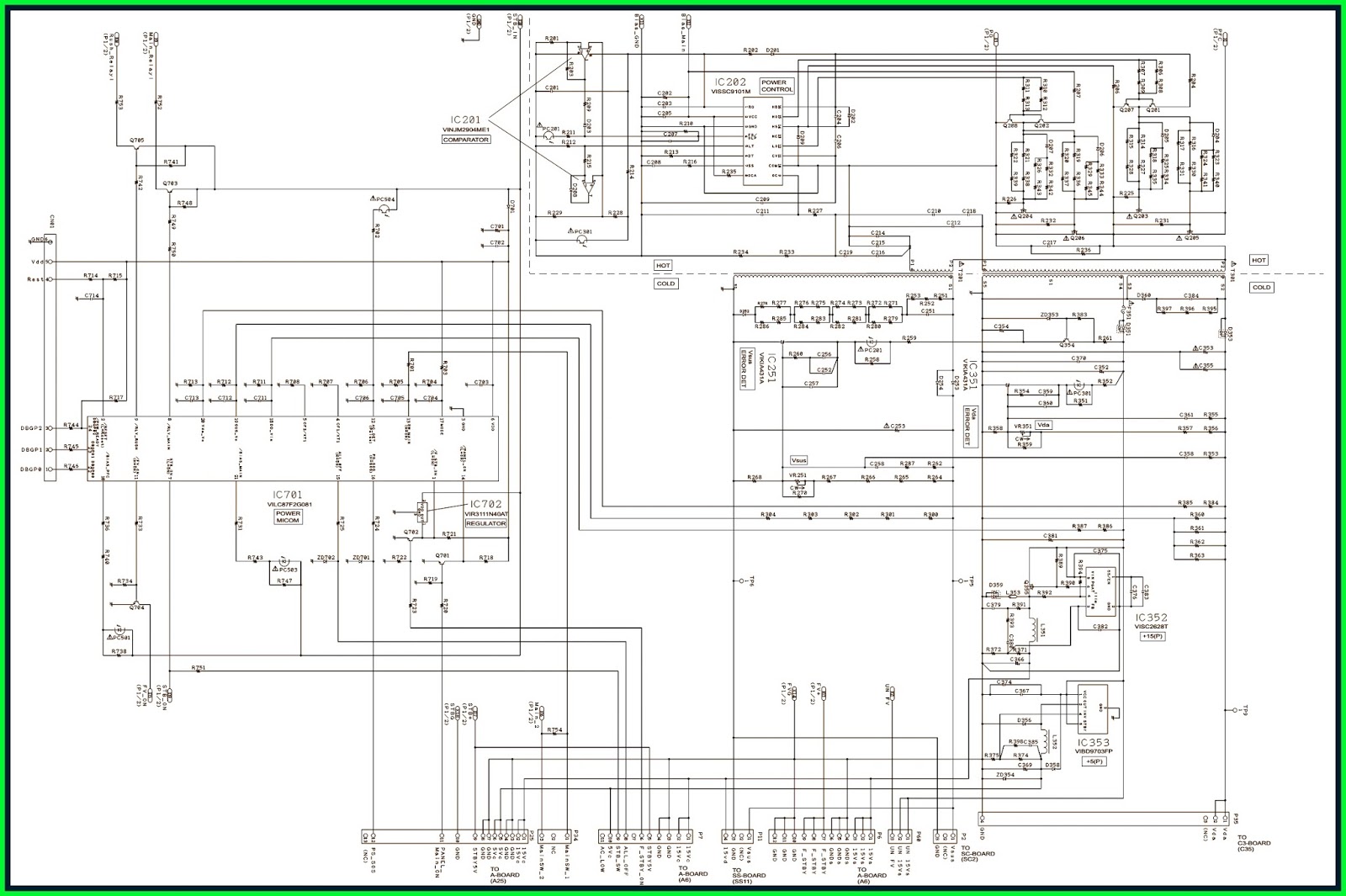
CLICK ON THE IMAGE TO ZOOM IN