 SONY KDS-50A3000 - KDS-55A3000 - KDS-60A3000 SERVICE MODE SELF DIAGNOSING AND POWER SUPPLY CIRCUIT

SONY KDS-50A3000 - KDS-55A3000 - KDS-60A3000
SERVICE MODE SELF DIAGNOSING AND POWER SUPPLY CIRCUIT
SELF-DIAGNOSTIC
FUNCTION
The units in this manual contain a
self-diagnostic function. If an error occurs, the POWER LED will automatically
begin to flash. The number of times the LED fl ashes translates to a probable
source of the problem. A definition of the POWER LED fl ash indicators is listed
in the instruction manual for the user’s knowledge and reference. If an error
symptom is
difficult to reproduced use the Remote
Commander to display the record that is stored at the internal NVM to specify
the cause of the failure.
Diagnostic Test Indicators
When an error occurs, the POWER LED will flash a set number of times to indicate the possible cause of the problem. If there is more than one error, the POWER LED will identify the first of the problem areas. If the errors occur simultaneously, the one that corresponds to the fewest fl ashes is identified first.
Results for all of the following diagnostic items are displayed on screen. (No error has occurred if the screen displays a “0”.)
NUMBER OF TIMES
LED BLINKS |
SELF CHECK CODE
|
DIAGNOSIS ITEM
|
POSSIBLE CAUSE
|
POSSIBLE SOLUTION
|
2 times
|
POW_OVP
|
Power OVP
|
7V is over voltage
|
Check CN6903 on G Board
|
3 times
|
POW_ERR1
|
Power Error
|
12V is not supplied
|
Check CN6903 on G Board
|
5 times
|
LAMP_DRV
|
Lamp Driver
|
Problem with the lamp driver
|
Check Power Supply (Ballast)
400V (CN6501 on G Board) Check IC4001 on FB1A Board |
6 times
|
COVER
|
Lamp Cover
|
Lamp cover is not securely
attached |
Secure Lamp Door.
Verify harness is connected to T Board. |
7 times
|
TEMP_ERR
|
Temperature Over
|
Inner temperature is too high
|
Remove dust from fan and
ventilation is clear. |
8 times
|
AUD_PROT
|
Audio Protect Error
|
Short in speaker line
|
Check A Board or replace speaker
|
9 times
|
FAN_ERR
|
Fan Error
|
Fan is not getting power.
Fan connector is not securely attached. |
Secure harness to fan.
Check CN4001 or CN5602 on FB1A Board. Check CN6900 on G Board. |
10 times
|
DTT_ERR
|
Microprocessor Error
|
DTT_WDT (Watch Dog Timer)
|
Check FB1A Board
|
11 times
|
DEV_ERR
|
Device Error
|
I2C Communication Error
|
Check S2, H2, and C Boad and all
connection to the FB1A Board |
LAMP-LED flashes
|
Lamp Error
|
Lamp needs to be replaced.
|
Change the lamp.
|
SELF-DIAGNOSTIC SELF CHECK SCREEN
1. TV must be in standby mode. (Power off).2. Press the following buttons on the Remote Commander within a second of each other:
DISPLAY >Channel 5 > Volume - >
POWER
CLEARING THE SELF-DIAGNOSTIC SCREEN
The self-diagnostic results displayed on the screen are not cleared automatically, therefore you should always check the self diagnostic screen during repairs. When you have completed the repairs, clear the self-diagnostic screen to reset the results to “0”.
Note: The self-diagnostic function will not be able to detect any subsequent faults after completion of the repairs unless the Self-Diagnostic result display is cleared to reset the results to “0”.
1. If the Self-Diagnostic screen is already displayed, proceed to step 3. If not, Power off (Set to Standby mode).
2. Press DISPLAY > Channel 5 > Volume - >POWER
3. Press Channel 8 > 0 The status resets to 0.
4. To exit the Self-Diagnostic screen, turn the power off.
SERVICE MODE
ACCESSING SERVICE ADJUSTMENT MODE
1. TV must be in standby mode. (Power off).
2. Press the following buttons on the Remote Commander within a second of each other:
2. Press the following buttons on the Remote Commander within a second of each other:
DISPLAY > Channel 5 > Volume + > POWER
VIEWING THE SERVICE MENUS
Use the Remote Commander to view the BE and Digital service menus options.
To display the Service Menu that contains the Category you want to adjust, press JUMP on the Remote Commander.
Use the Remote Commander to view the BE and Digital service menus options.
To display the Service Menu that contains the Category you want to adjust, press JUMP on the Remote Commander.
ADJUSTING H/V CENTER
Check the picture horizontal/vertical center after replacing the Optics Unit Block or Rear Cover.
1. Check the H/V center using a 480i monoscope signal with the TV in “FULL’ model.
2. If the center is shifted, proceed to step 3.
3. Access the Service Menu by pressing the following buttons on the Remote Commander within a second:
DISPLAY > Channel > 5 > Volume + >TV POWER .
The service menu displays.4. Press the JUMP button until the BEM micro service menu displays.
5. Press 2 until the 0016 TG category displays.
6. Press 1 until the 0003 VCENT item displays.
7. Press 3 to increase (shift VCENT up), or
press 6 to decrease the value (shift VCENT down) until the correct adjustment
is set.
8. Press 1 until the 0004 HCENT item displays.
8. Press 1 until the 0004 HCENT item displays.
9. Press 3 to increase (shift HCENT right), or
press 6 to decrease the value (shift HCENT left) until the correct adjustment
is set.
10. To write into memory, press MUTING then 0 on the Remote Commander.
10. To write into memory, press MUTING then 0 on the Remote Commander.
EXITING SERVICE MODE
After completing the changes, exit service mode.To exit service mode, turn the power off by pressing POWER . Wait 2 minutes before restarting the set to allow the fans to completely shut down or the Service Menu will appear on the screen.
POWER SUPPLY CIRCUIT
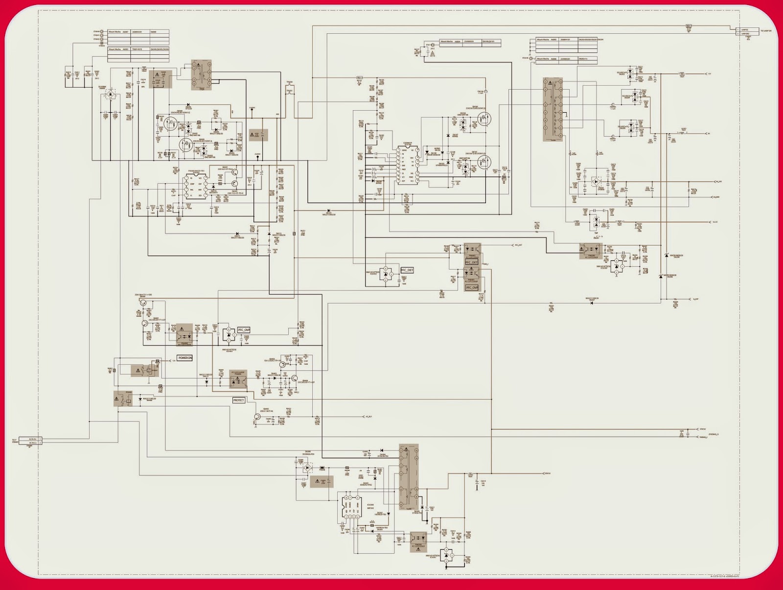
CLICK ON THE IMAGE TO ZOOM IN