
Remote control - RRMCG1559CESA
2. Push on the six hooks (2) of the cabinet B and open it slightly.
3. Disconnect all the connectors (3) from the terminal and operation PWBs. Detach the cabinet B.
4. Disconnect all the connectors (4) from the main PWB.
6. Peel off the five pieces of tape (6) and detach the LC display unit.
7. Remove the two lock screws (7) off the remote control PWB.
8. Remove the four lock screws (8) off the terminal PWB.
9. Remove the two lock screws (9) off the operation PWB.
10. Remove the two lock screws (10) off the flexible shield, and detach he relay PWB.
12. Undo the seven hooks (12) to release the unit frame.
13. Detach the fluorescent lamp (13).


AC adapter: UADP-0211CEZZ
DC power supply: 12 +/-- 0.5V
[Procedure]
Connect TP2001 and TP2002 to GND, and turn on the power.
• The initialization of microcomputer is as follows.
• AV position, DAC data, G/A data, sound processor data, and video chroma data adjustment values are taken as defaults.
Short-circuit TP2001 to GND, and turn on the power.
Or short-circuit TP2002 to GND, and turn on the power.
Or holding down the [TV/VIDEO] key and [MENU] key, turn on the main power, and simultaneously press the (inspection process) [CH DN] key and [VOL– ] key to change the mode to the adjustment mode.
The manual adjustment or adjustment through communication with the automatic machine is performed.
[Procedure]
Holding down the [TV/VIDEO] key and [MENU] key, turn on the power.
• VOLUME, PICTURE, TINT (only NTSC), COLOR, BLACK LEVEL, SHARPNESS, RED-BLUE, GREEN change as follows.
If TV is indicated as SETTING COMPLETE, setting has been completed.


Sharp LC 10 A2U How to disassemble, Adjustment mode, schematic diagram (Circuit Diagram) LCD COLOR TELEVISION
ADJUSTING PROCEDURE
Preparation for Adjustments
Use the exclusive-use AC adapter or stable DC power supply.
AC adapter: UADP-0211CEZZ
DC power supply: 12 ± 0.5V.
Special mode setting procedure
After initialization of E2PROM the mode is changed to the adjustment mode.
[Procedure]
Connect TP2001 and TP2002 to GND, and turn on the power.
[Description]
• The initialization of microcomputer is as follows.
• AV position, DAC data, G/A data, sound processor data, and video chroma data adjustment values are taken as defaults.
(2) Adjustment mode
[Procedure]
Short-circuit TP2001 to GND, and turn on the power.
Or short-circuit TP2002 to GND, and turn on the power.
Or holding down the [TV/VIDEO] key and [MENU] key, turn on the main power, and simultaneously press the (inspection process) [CH DN] key and [VOL– ] key to change the mode to the adjustment mode.
[Description]
The manual adjustment or adjustment through communication with the automatic machine is performed.
(3) Inspection mode
[Procedure]
Holding down the [TV/VIDEO] key and [MENU] key, turn on the power.
[Description]
• In the ordinary menu select “VIDEO ADJUST” with the [CH] key, and decide with the [VOL] key. Then select “PICTURE”, “TINT (only NTSC)”, “COLOR”, “BLACK LEVEL”, “SHARPNESS”, “RED-BLUE”, “GREEN” and “COLOR SYSTEM” with the [CH] key, and decide with the [VOL] key. After that, adjust values with the [VOL] key.
• VOLUME, PICTURE, TINT (only NTSC), COLOR, BLACK LEVEL, SHARPNESS, RED-BLUE, GREEN change as follows.


(4) Shipping setting mode
[Procedure]
Holding down the [TV/VIDEO] key and [MENU] key, turn on the main power, and simultaneously press the (inspection process) [CH UP] key and [VOL+] key to change the mode to the adjustment mode.
[Description]
User adjustment and other values are taken as defaults.
If TV is indicated as SETTING COMPLETE, setting has been completed.
Cancel of special mode
Turn off the main unit power.
Adjustments and shipping settings list

Troubleshooting table


DISASSEMBLY OF THE SET
1. Remove the five lock screws (1) off the cabinet B.
2. Push on the six hooks (2) of the cabinet B and open it slightly.
3. Disconnect all the connectors (3) from the terminal and operation PWBs. Detach the cabinet B.
4. Disconnect all the connectors (4) from the main PWB.
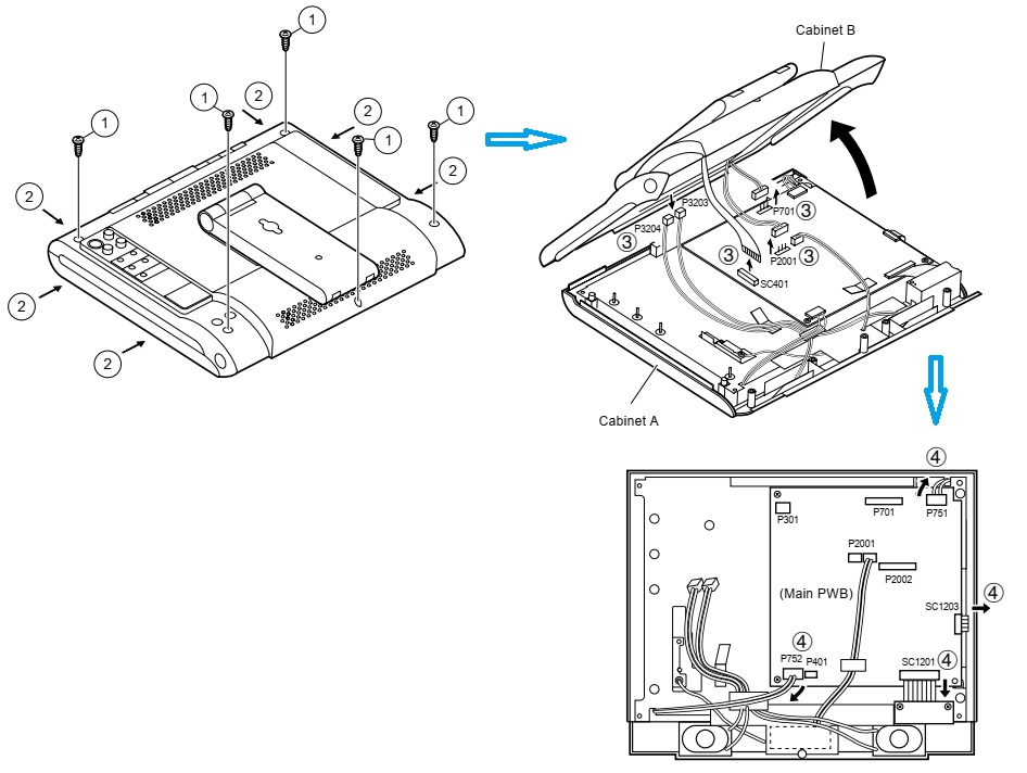
5. Remove the four lock screws (5) off the main PWB.
6. Peel off the five pieces of tape (6) and detach the LC display unit.
7. Remove the two lock screws (7) off the remote control PWB.
8. Remove the four lock screws (8) off the terminal PWB.
9. Remove the two lock screws (9) off the operation PWB.
10.Remove the two lock screws (10) off the flexible shield, and detach he relay PWB.

11.Remove the lock screw (11) off the LC display unit.
12.Undo the seven hooks (12) to release the unit frame.
13.Detach the fluorescent lamp (13).
