 LG 42PJ150 - Plasma TV - Adjustments - How to adjust Va and VS voltages at Power Supply

LG
42PJ150 - LG 42PJ150-ZE – Plasma TV - Adjustments - Audio output schematic
North/Latin
America - Europe/Africa - Asia/Oceania
(1) The
adjustment is according to the order which is designated and which must be
followed, according to the plan which can be changed only on agreeing.
(2) If there is no specific designation, the adjustment must be performed in the circumstance of 25 °C ± 5 °C of temperature and 65 % ± 10 % of relative humidity.
(3) The input voltage of the set must keep 100 V ~ 240 V, 50 / 60 Hz.
(4) Input signal Unit: Product Specification Standard.
(5) The set must be operated for about 5 minutes prior to the adjustment.
After
turning on RGB Full Window pattern in HEAT-RUN Mode, the receiver must be
operated.
Enter into HEAT-RUN MODE
1) Press the ‘POWER ON’ button on R/C for adjustment.
2) Press the ‘ADJ’ button on R/C and enter EZ ADJUST Select “7. Test Pattern” by using Up/Dn (CH +/-) and press ENTER.
Select “White” by using Right / Left (VOL +/-) and press ENTER.
Enter into HEAT-RUN MODE
1) Press the ‘POWER ON’ button on R/C for adjustment.
2) Press the ‘ADJ’ button on R/C and enter EZ ADJUST Select “7. Test Pattern” by using Up/Dn (CH +/-) and press ENTER.
Set
heat run should be activated without a signal generator.
Single color patterns (RED / BLUE / GREEN) of HEAT RUN MODE are used to check a plasma panel.
Single color patterns (RED / BLUE / GREEN) of HEAT RUN MODE are used to check a plasma panel.
Caution:
If you turn on a still screen more than 20 minutes (Especially digital pattern,
cross hatch pattern), an after image may be made in the black level part of the
screen.
Use
‘power on’ button of a service R/C to power on TV set.
Do not connect any external input cable if there is no any specifics.
Update S/W using Auto Download through the USB
Do not connect any external input cable if there is no any specifics.
Caution: S/W version of USB file (xxx.epk) must be bigger than one which is downloaded previously.
(1) Insert the USB stick to the USB socket.
(2) A downloaded file in USB stick will be detected automatically.
(3)
If S/W version of USB file (xxx.epk) is bigger than one which is
downloaded previously, the message, “Copying files from memory”, will
appear.
(4) If an update procedure was completed, TV set will be turned off and on automatically.
(5) If TV set is turned on, check an updated version.
*
If a downloaded version is bigger than one of which TV set had, TV set
can lost channel data. In this case, you have to scan channels again.
After Downloading S/W, Adjust
TOOL OPTION
(1) Push “IN-START” button on a service R/C.
(2) Select “Tool Option 1” and Push “OK” button.
(3) Put the number of a below table in order of a suffix of the “Tool Option(X)”. (Each model has a different number.)

POWER Supply Unit PCB Ass’y Va/Vs Voltage Adjustment
(Both Vs and Va voltage adjustment are necessary.)
Va/Vs Adjustment Procedure
(1) Connect positive(+) terminal of DMM to Vs/Va pin, connect negative(-) terminal to GND.
(2)
Turning ‘Vs/Va Adjust’ and adjust Vs/Va voltages to a value which is
written on a right/top label of a module. (deviation ; ±0.5V)
[Caution]
Each
Power Supply Unit PCB assembly must be checked by check JIG set.
(Because power PCB Ass’y damages to PDP Module, especially be careful)
Set up “RF mode(noise)” before a voltage adjustment.
Test equipment: DMM 1EA

PCMCIA CARD Check
You must adjust DTV 29 Channel and insert PCMCIA CARD to socket.
If PCMCIA CARD works normally, video signals will appear on screen.
But it works abnormally, “No CA module” will appear on screen.
[ Caution: Set up “RF mode” before launching products.]
White Balance Adjustment
Caution: Press the POWER ON KEY on R/C before W/B adjustment.
Test Equipment
Color Analyzer (CS-1000, CA-100+(CH.10), CA-210(CH.10))
Adjust CA-100+ / CA-210 by CS-1000 before measuring
You
should use Channel 10 which is Matrix compensated (White, Red, Green,
Blue revised) by CS-1000 and adjust in accordance with White balance
adjustment coordinate.
Manual W/B Adjustment
(1) Execute the zero calibration of CA-100+ / CA-210.
(2) Press the ‘ADJ’ button on a service R/C and enter EZ ASJUST by selecting ‘6. White Balance’.
(3) Then, 216 gray pattern will appear on the screen.
(4) Change the R/G/B-Gain as passing in 3 color coordinates and temperatures, COOL, MEDIUM and WARM.
< Temperature: COOL >
- R-Cut / G-Cut / B-Cut is set to 64
- Control R-Gain and G-Gain.
- Each gain is limited to 192
< Temperature: MEDIUM >
- R-Cut / G-Cut / B-Cut is set to 64
- Control R-Gain and G-Gain.
- Each gain is limited to 192
< Temperature: WARM >
- R-Cut / G-Cut / B-Cut is set to 64
- Control G-Gain and B-Gain.
- Each gain is limited to 192
(5) Press ‘EXIT’ button on a service R/C.
Serial Number Download
Download Procedure
(1) Press “Power on” button of a service R/C.(Baud rate : 115200 bps)
(2) Connect RS232-C Signal Cable.
(3) Write Serial number through RS-232C.
(4) Check the serial number at the Diagnostics of ‘SETUP’menu.
[Don’t
download HDMI/RGB EEPROM to write a model name. Model name dois
unnecessary because this model use ‘Tool Option’ to call a model name.]
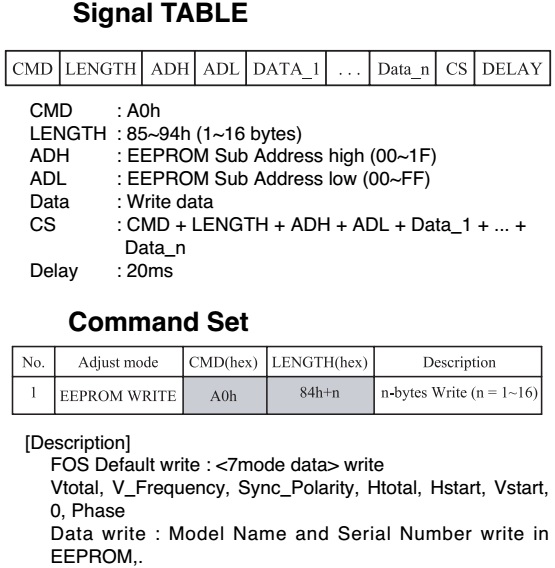
Signal TABLE
CMD : A0h
LENGTH : 85~94h (1~16 bytes)
ADH : EEPROM Sub Address high (00~1F)
ADL : EEPROM Sub Address low (00~FF)
Data : Write data
CS : CMD + LENGTH + ADH + ADL + Data_1 + ... + Data_n
Delay : 20ms.
ComFOS Default write : <7mode data> write
Vtotal, V_Frequency, Sync_Polarity, Htotal, Hstart, Vstart, 0, Phase
Data write : Model Name and Serial Number write in
EEPROM,mand Set.
Audio output schematic

CI+
Key Download

Download Procedure
(1) Press "Power on" button of a service R/C.(Baud rate : 115200 bps)
(2) Connect RS232-C Signal Cable.
(3) Write CI+ Key through RS-232-C.
(4) Check whether the key was downloaded or not at ‘In Start’ menu.
Check
Information (Serial No. & Model name)
(1) Push the menu button in DTV mode.
(2) Select the SETUP => Diagnostics => To set
(3) Check the Serial Number.
(1) Push the menu button in DTV mode.
(2) Select the SETUP => Diagnostics => To set
(3) Check the Serial Number.
A high definition [CRO] test pattern can be send to viewers, if they send their email ID