 SHARP LC-70UD1U - 2k/4k - SERVICE TRAINING –SERVICE MODE – LED BLINKING AND TROUBLE SHOOTING

SHARP LC-70UD1U
LED LCD 4K UHD (20160p)
120Hz ACTIVE 3D
SMART TV
SERVICE TRAINING –SERVICE MODE AND – LED BLINKING AND TROUBLE SHOOTING
What is 4K
The new 4K technology is now entering living rooms around
the world.
• It is double the resolution of 2K technology, or 1920x1080 = 3840x2160.
• All signal is first up scaled to 1920x1080, enhanced, and then scaled to 3840x2160.
• Native signal at 3840x2160 is not up scaled or enhance.
• It is double the resolution of 2K technology, or 1920x1080 = 3840x2160.
• All signal is first up scaled to 1920x1080, enhanced, and then scaled to 3840x2160.
• Native signal at 3840x2160 is not up scaled or enhance.
Rear Cabinet Removal
The Rear Cabinet is removed with the
set on it’s stand.
# Remove 3 short machine screws and lift off stand cover (green)
# Remove 28 machine screws (red).
#Remove 4 plastic screw (yellow).
# Remove 3 short machine screws and lift off stand cover (green)
# Remove 28 machine screws (red).
#Remove 4 plastic screw (yellow).

Lift off Cord Cover Squeeze
AC connector and remove cord.
Lift off Rear Cabinet,
Note: If set is totally dead when you arrive on site, please check AC cord first and be sure the it is locked in place.
Note: If set is totally dead when you arrive on site, please check AC cord first and be sure the it is locked in place.

# Here is a view with the rear Mcabinet removed.

Sub-Woofer Removal
# Remove 4 machine screws.
# Disconnect speaker wire.
# Lift off Sub-Woofer Ass’y
# This will give you access to the DRC/FRC and TCON section
# Disconnect speaker wire.
# Lift off Sub-Woofer Ass’y
# This will give you access to the DRC/FRC and TCON section

PWB Layout

Connection Layout

# The power unit is responsible for providing main
and back-up power sources, including LED backlight drive.
# UR13 Volts = Unregulated 13 Volts / switched
# S13 Volts = Signal 13 Volts regulated / switched
# BU5 Volts = Back-Up 5 volts / unswitched (always supply)
# 12 Volts PNL= Panel Power 12 Volts / switched
# UR13 Volts = Unregulated 13 Volts / switched
# S13 Volts = Signal 13 Volts regulated / switched
# BU5 Volts = Back-Up 5 volts / unswitched (always supply)
# 12 Volts PNL= Panel Power 12 Volts / switched

The main PWB is responsible for the following operations:
#HDMI Input Switching & Processing.
#HDMI 1 (*ARC) HDMI 4 (**MHL)
#Component and Composite Input terminals.
#USB Input Terminals
#A/V Switching.
#Analog, Cable and Digital Tuning (ATSC/QAM).
#Analog & Digital Audio Processing (SIF & SAP).
#Optical Digital Audio Output.
#CPU, EEPROM, & RS232 Operations.
#CAT 5 Internet connection.
#Monitor/SubMicon.
#Audio Amplifier.
* Audio Return Channel
** Mobile High Definition Link (for charging mobile devices.)

# U+5V
# D+5V
# D+3.3V
# D+1.5V
# D+1.2V
# BU+3.3V
# Backlight error detection
# 12V panel power detection
# D+5V
# D+3.3V
# D+1.5V
# D+1.2V
# BU+3.3V
# Backlight error detection
# 12V panel power detection
U+5V and UR+13V from the power unit is applied
to the main PWB to start up the set.
LED Drive Operation
# The LED drive unit is responsible for
providingLED drive voltage for the edge lit display.

DRC/FRC/TCON Operation
# DRC: Dynamic Range Compression Receives LVDS
from Main PWB which was converted to 2k when content is at a
lower resolution then 1080.
# DRC enhances image before converting to 4K.
# 4 K resolution = 3,840 x 2,160, which is double from 1920x1080.
# DRC adds 3 pixels for every single pixel with 1080 I/P video sources.
# FRC converts the 60hz LVDS to 120Hz.
# 4 LCD drive signals lines directly output the LCD controller at 210MHz PPDS format, which drives the 10bit LCD panel.

# Remove 8 cables
# Remove 8 chrome screws (red)
# Lift off Terminal Angle Side and Terminal Angle Bottom, lift out Main PWB.
# Please Note: At the time of publication, this model does not use MDL files for Main Unit set-up.
pic11
# Remove 8 chrome screws (red)
# Lift off Terminal Angle Side and Terminal Angle Bottom, lift out Main PWB.
# Please Note: At the time of publication, this model does not use MDL files for Main Unit set-up.
pic11
Main PWB Installation
Entering the adjustment process
mode
1) Press and continue to hold the VOL DOWN & INPUT buttons while plugging in AC power.
2) Continue to hold the VOL DOWN & INPUT buttons until <K> appears on the top left side of the Display.
1) Press and continue to hold the VOL DOWN & INPUT buttons while plugging in AC power.
2) Continue to hold the VOL DOWN & INPUT buttons until <K> appears on the top left side of the Display.


5) Select Panel Limit and press
left arrow on remote control to turn Panel Limit OFF.


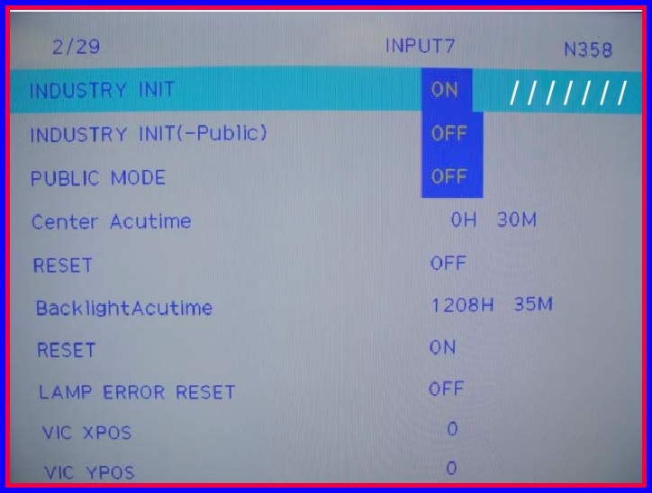
11) Complete the main PWB installation by running Industry
INIT and finally, check and reset lamp errors.

# Note: This set has 1 lamp error, so the set will still operate normally.
# Please follow the next steps on how to reset lamp errors.
# Please follow the next steps on how to reset lamp errors.

How to Perform Lamp Error Reset
1) Press DOWN key on remote control
and navigate to page 2/29.
2) Press > Key on the remote control to change from off to
on.


4) Press DOWN key on remote control
and navigate to page 2/29.
5) Press > key on the remote control to change from off to on.
5) Press > key on the remote control to change from off to on.

# Note:////// will appear during industry init process.

1. All changes are stored automatically upon
input.
2. Disconnect AC power to exit the service menu.
2. Disconnect AC power to exit the service menu.
Power Unit Removal
# Disconnect 4 cables.
# Remove 8 chrome screws and lift off the Power Unit.
# Remove 8 chrome screws and lift off the Power Unit.

Before you can access the DRC/FRC
and Tcon Units, you will need to remove the shield.
#Remove 6 black machine screws and lift off the shield.
#Remove 6 black machine screws and lift off the shield.

#Remove 12 chrome screws and lift off the DRC/FRC Unit.

#Disconnect 7 cables
#Remove 6 Chrome screws and lift off the LCD Control Unit.
#Remove 6 Chrome screws and lift off the LCD Control Unit.

# Disconnect 3 cables.
#Remove 8 black screws and lift off the LED Drive PWB.
#Remove 8 black screws and lift off the LED Drive PWB.

1. Unplug the AC cord
2. Insert the USB Memory Device with the Main Software Upgrade into the side terminal
3. Plug in the AC cord while holding down power button on the unit for ~5 seconds
4. After the unit powers up a screen will be displayed showing the upgrade progress as in Figure 1
5. Once the upgrade is complete the screen will display an “UPGRADE SUCCESS” message. as in Figure 2


Upgrade Failure
# In the event the upgrade fails an
“UPGRADE FAILURE” message will be displayed.
# In this event of an Upgrade Failure please try to perform upgrade again.
# If the upgrade fails after multiple attempts verify that the USB Memory Device only has 1 software file update on it. The USB Memory Device will have 2 files if a monitor update is required.

Troubleshooting
Flashing Power / Timer LED
In most of our past models a faulty,
loose, or disconnected LVDS cable can lead to errors, such as
“Power Icon” 2 slow and 5 fast, or 2 “Power”, 5 “OPC”, etc. However,
LC70UD1U will behave in the following manner.
# No error Blink Codes.
# Black screen, no backlights.
# Relay click ~ 15 seconds and set powers down.
# Monitor Error 02 will be stored in the service menu.
# No error Blink Codes.
# Black screen, no backlights.
# Relay click ~ 15 seconds and set powers down.
# Monitor Error 02 will be stored in the service menu.

Troubleshooting Flashing Power / Timer LED

Troubleshooting LED Backlight Failure
# If the Power and Timer LED’s indicate lamp errors,
try the following troubleshooting methods.
# Force the set on using Ch DOWN Vol UP while plugging in ac power cord.
# If the set turns on, look for backlight illumination.
# If set does not turn on, Remove L1 and L2 independently, and force-on. If unit turns on the LED backlight is most likely at fault.
# Force the set on using Ch DOWN Vol UP while plugging in ac power cord.
# If the set turns on, look for backlight illumination.
# If set does not turn on, Remove L1 and L2 independently, and force-on. If unit turns on the LED backlight is most likely at fault.
Note: The set will run for ~ 10 seconds With
L1 or L2 disconnected. Then the set will shut down. This will prove a
bad LED strip inside the LCD panel.
Troubleshooting LCD Panel
# LCD Test Pattern bypasses the Main PWB. The test
pattern is generated from the LCD controller and a applied
directly to the LCD panel
1. Navigate to page 18/29 of the Service Menu.
2. Press “>” button on the remote control to enter the LCD TEST PATTERNS
1. Navigate to page 18/29 of the Service Menu.
2. Press “>” button on the remote control to enter the LCD TEST PATTERNS

# The TV test pattern is generated on the Main PWB
and applies the test
pattern to the LCD Controller.
1. Press the “Volume –” button on the remote control to scroll through test patterns
pattern to the LCD Controller.
1. Press the “Volume –” button on the remote control to scroll through test patterns
