REPAIRING AND NOT THROWING AWAY

Richtige Fernseher haben Röhren!

Richtige Fernseher haben Röhren!

In Brief: On this site you will find pictures and technical information about Service Modes, Circuit Diagrams, Firmware Update procedure, Disassemble procedure, Universal remote control set-up codes, Troubleshooting and more....

If you go into the profession, you will obtain or have access to a variety of tech tips databases HERE IT IS Master Electronics Repair !.

These are an excellent investment where the saying: 'time-is-money' rules. However, to learn, you need to develop a general troubleshooting approach - a logical, methodical, method of narrowing down the problem. A tech tip database might suggest: 'Replace C536' for a particular symptom. This is good advice for a specific problem on one model. However, what you really want to understand is why C536 was the cause and how to pinpoint the culprit in general even if you don't have a service manual or schematic and your tech tip database doesn't have an entry for your sick TV or VCR.

While schematics are nice, you won't always have them or be able to justify the purchase for a one-of repair. Therefore, in many cases, some reverse engineering will be necessary. The time will be well spent since even if you don't see another instance of the same model in your entire lifetime, you will have learned something in the process that can be applied to other equipment problems.
As always, when you get stuck, checking out a tech-tips database may quickly identify your problem and solution.In that case, you can greatly simplify your troubleshooting or at least confirm a diagnosis before ordering parts.

Happy repairing!
Today, the West is headed for the abyss. For the ultimate fate of our disposable society is for that society itself to be disposed of. And this will happen sooner, rather than later.

How to use the site:

- If you landed here via any Search Engine, you will get what you searched for and you can search more using the search this blog feature provided by Google. You can visit more posts scrolling the left blog archive of all posts of the month/year,
or you can click on the main photo-page to start from the main page. Doing so it starts from the most recent post to the older post simple clicking on the Older Post button on the bottom of each page after reading , post after post.

You can even visit all posts, time to time, when reaching the bottom end of each page and click on the Older Post button.

- If you arrived here at the main page via bookmark you can visit all the site scrolling the left blog archive of all posts of the month/year pointing were you want , or more simple You can even visit all blog posts, from newer to older, clicking at the end of each bottom page on the Older Post button.
So you can see all the blog/site content surfing all pages in it.

- The search this blog feature provided by Google is a real search engine. If you're pointing particular things it will search IT for you; or you can place a brand name in the search query at your choice and visit all results page by page. It's useful since the content of the site is very large.

Note that if you don't find what you searched for, try it after a period of time; the site is a never ending job !

..............The bitterness of poor quality is remembered long after the sweetness of todays funny gadgets low price has faded from memory........ . . . . . .....
Don't forget the past, the end of the world is upon us! Pretty soon it will all turn to dust!

©2010, 2011, 2012, 2013, 2014 Frank Sharp - You do not have permission to copy photos and words from this blog, and any content may be never used it for auctions or commercial purposes, however feel free to post anything you see here with a courtesy link back, btw a link to the original post here , is mandatory.
All posts are presented here for informative, historical and educative purposes as applicable within fair use. NOTHING HERE IS FOR SALE !

Tuesday 12 February 2019

ACER - AT 3705 _ LCD TV _ DISASSEMBLE METHOD FULL GUIDE


  ACER - AT 3705 _ LCD TV _ DISASSEMBLE METHOD FULL GUIDE

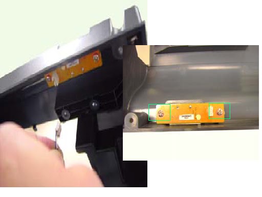
 REMOVING THE SPEAKER.

  • Press the latch to release speaker cable.
  • Remove 4 screws securing the right speaker.
  • Remove the right speaker.
  • Repeat the same steps for left speaker.
  • Remove the 4 screws securing the right speaker bracket and remove it from speaker.
  • Repeat the same steps for left speaker.

REMOVING THE TV STAND MODULE
  • Remove the 4 screws securing the TV stand module.
  • Remove the stand module.


REMOVING THE I/O
  • Remove 6 screws securing the I/O cover.
  • Remove the I/O cover.

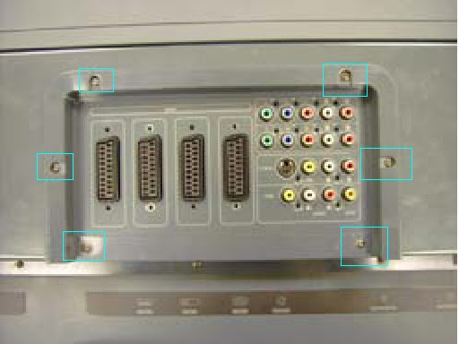
  • Remove 20 screws securing the I/O bracket.
  • Remove the bracket.

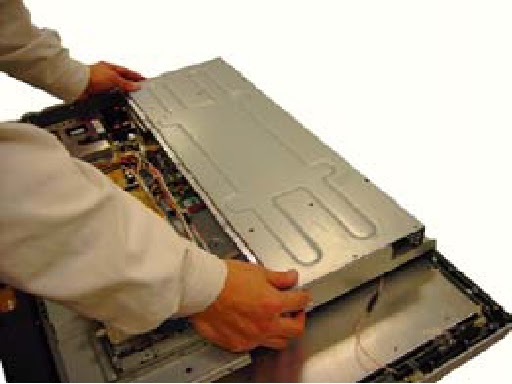
REMOVING DOWN COVER.

  • Remove 5 screws securing the down cover.
  • Remove 4 nuts securing the down cover.


  • Push down cover a little bit backward.
  • Remove the down cover as shown.

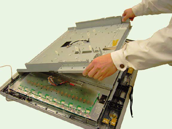
  • Remove 20 screws securing back cover.
  • Lift the back cover up.
  • Remove the 2 screws securing the left speaker board.
  • Remove the 2 screws securing the right speaker board.
  • Disconnect the right speaker connector from the back cover.

  • Remove back cover as shown.

REMOVING TOP SHIELDING
  • Remove the screws securing the top shielding.
  • Push the top shielding a little bit upward.
  • Remove the shielding.  

  REMOVING THE DMA BOARD.

  • Disconnect the following connectors and antennas.
  • Remove 6 screws securing the DMA board, and remove it.


REMOVING POWER BOARD

  • Disconnect the connectors from the Power Board.
  • Remove 9 screws securing the Power Board and the Remote Power Board.


REMOVING CONVERTER BOARD

  • Disconnect connectors from the converter board.


  • Remove 4 screws securing the converter board.
  • Remove the converter board.


REMOVING AUDIO BOARD
  • Disconnect cables from audio board.
  • Remove 4 screws securing audio board.
  • Remove audio board. 


REMOVING THE I/O BOARD AND A-TUNER BOARD.
  • Disconnect the connectors from I/O board.
  • Remove 4 screws securing I/O board, and 4 screws securing the A-Tuner board.

  • Remove the I/O board and A-Tuner board.
  • Separate the I/o board and A-Tuner board. 


REMOVING THE HEAT SINK
  • Remove the 4 screws securing the heat sink.
  • Remove the heat sink from main unit.


REMOVING THE ETHERNET BOARD
  • Remove 2 screws securing the Ethernet board.
  • Remove the Ethernet board.

  • Disconnect the cable from Ethernet board.
  • Remove 2 screws securing the Ethernet bracket and remove the bracket.


REMOVING THE D-TUNER
  • Remove 3 screws securing the D-Tuner.
  • Remove the D-Tuner.


REMOVING THE M/B & D-TUNER BOARD
  • Disconnect cables from Main baord and D-Tuner.
  • Remove 4 nuts and 2 screws securing the Main board.

  • Remove the 2 screw, 3 short nuts and 4 long nuts securing D-tuner board.
  • Remove the Main Board and D-tuner board.
  • Separate the Main Board & D-tuner board.

REMOVING THE CARD READER MODULE
  • Remove 3 screws securing the card reader module.
  • Remove 2 screws securing the ground wire.
  • Turn the card reader module over and disconnect the cables from card reader module.
  • Disconnect the cables from AV3 board.
  • Remove the 2 screws securing the AV3 board and remove it from card reader module.

REMOVING THE BEZEL SKIRT
  • Remove 6 screws securing the bezel skirt.
  • Remove bezel skirt.
REMOVING THE IR BOARD, POWER BUTTON AND KEYPAD BOARD.
  • Remove the 2 screws securing the keypad board and remove it.
  • Remove the two screws securing IR board, and remove 2 screws securing the Power button board.

REMOVING PCB CHASSIS
  • Disconnect cables from LVDS board.
  • Remove 7 screws  on the chassis bottom view.

  • Remove 10 screws on chassis top view.
  • Remove the PCD chassis as shown.

REMOVING ANTENNA
  • Open the clip to release the antenna.
  • Remove antenna.

REMOVING LCD PANEL
  • Remove the 2 screws on the right.
  • Remove the 2 screws on the left
  • Remove the LCD panel
  • remove 2 screws securing the right side bracket.
  • Remove 4 screws securing the down bracket.
  • Remove the right side bracket.
  • Remove the down bracket.
  • Repeat the same steps for left side and top bracket.