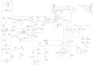
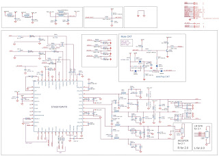
 Philips 22HFL3027W LED LCD TV – Power supply 715G5309 and audio output schematic
If a board is defective, consult your
repair technician to decide if the board has to be exchanged or if it
can be repaired on component level.If your repair technician says the board should be exchanged completely, do not solder on the defective board. Otherwise, it cannot be returned to the O.E.M. supplier for back charging.
Power Supply Unit
All power supplies are a black box for Service. When defective, a new board must be ordered and the defective one must be returned, unless the main fuse of the board is broken. Always replace a defective fuse with one with the correct specifications. This part is available in the regular market. Consult the Philips Service web portal for the order codes of the boards.
Important delta’s with the xxHFL30xxx/10platform are:
• New power architecture for LED backlight
• “Boost”-signal is now a PWM-signal + continuous variable.
The control signals are:
• Stand-by
• Lamp “on/off”
• DIM (PWM) (not for PSDL)
[No detailed information is available because of design protection issues.]
The output voltages to the chassis are:
• +5V-STANDBY (Stand-by mode only)
• +12V (on-mode)
• +Vsnd (+24V) (audio power) (on-mode)
• +24V (bolt-on power) (on-mode)
• Output to the display; in case of
- PSL and PSLS (LED-driver outputs)
- PSDL (high frequent) AC-current.
Diversity
The diversity in power supply units is mainly determined by the
diversity in displays.
The following displays can be distinguished:
LED backlight:
- side-view LED without scanning: PSL power board
- side-view LED with scanning: PSLS power board
- direct-view LED without 2D-dimming: PSL power board
- direct-view LED with 2D-dimming: PSDL power board
PSL stands for Power Supply with integrated LED-drivers.
PSLS stands for a Power Supply with integrated LED-drivers with added Scanning functionality (added microcontroller).
PSDL stands for a Power Supply for Direct-view LED backlight with 2D-dimming.
Connector overview
SMPS, Backlight inverter schematic
DC/DC Converters
The on-board DC/DC converters deliver the following voltages (depending on set execution):
• +5V2-STANDBY, permanent voltage for the Stand-by controller, LED/IR receiver and controls;
• +12V, input from the power supply for the panel common (active mode);
• +24V, input from the power supply for the amplifier;
• +1V1, core voltage supply for MTK5366; has to be started up first and switched “off” last
• +1V2, from the power supply for the scaler IC MT5366.
• +1V5, supply voltage for DDR3 (diagram B)
• +3V3, general supply voltage
• +5V-TUN, supply voltage for tuner
• +5V-USB, input intermediate supply voltage for USB Power
• +3V3 from the power supply for the scaler IC MT5366.
• +3V3, general supply voltage
• +5V-TUN, supply voltage for tuner
• +5V-USB, input intermediate supply voltage for USB Power
• +3V3 from the power supply for the scaler IC MT5366.
Audio output schematic
Click on the pictures to enlarge them


