 Philips 40PFL4609 – How to enter service mode – Software update – Power Supply (SMPS) Circuit diagram

Philips
40PFL4609 LED HDTV 40 inch – Firmware update – SMPS schematic – How to enter
Service Mode – How to initialize – White balance adjustment
Philips
40PFL4609/F8 (XA1) A4D2AMA - TYPE A
Philips
40PFL4409/F8 (XA1) A4G2EMA - TYPE B
How
to set up the service mode
1. Turn
the power on.
2. Press [0], [6], [2], [5], [9], [6] and [INFO] buttons on the remote control unit in this order. The following screen appears.
2. Press [0], [6], [2], [5], [9], [6] and [INFO] buttons on the remote control unit in this order. The following screen appears.
To exit, press [CH RETURN] or [PREV CH] button.

FIRMWARE
RENEWAL MODE
TYPE
A
1. Turn
the power off and unplug the AC Cord.
2. Insert the USB storage device to the USB port.
2. Insert the USB storage device to the USB port.
3.
Plug the AC Cord and turn the power on.
4. After few seconds, the menu mode will appear in the screen.
Note: After 30 seconds without an operation, the menu mode will disappear automatically. To display the menu mode again, press the [MENU] button on the remote control unit.
5. Select “Setup” and press the [OK] button to display the setup menu.
6. Select “Software”.
7. Select “Software update”.
8. Select “USB”.
9. Press the [OK] button on the remote control unit to enter the update mode.
[To cancel the update mode, select “Cancel”
and press the [OK] button.]
10.
Select the file and press [OK] button.
11. The update will start.
11. The update will start.
[If
the screen isn’t displayed, repeat from step 1.]
12.
Select “Yes” and press the [OK] button to update.
Note: Do not remove the USB storage device or turn the TV off while update is in progress.
13. When the firmware update is completed; and the status will be displayed.
Note: Do not remove the USB storage device or turn the TV off while update is in progress.
13. When the firmware update is completed; and the status will be displayed.
Remove
the USB storage device from the USB port.
Turn the power off and turn the power on again.
Turn the power off and turn the power on again.
TYPE
B
User
Upgrade (Filename example: TVNB2***_00_PH_XX91_FB1.bin)
Upgrade the firmware only. The setting values will not be initialized.
The User Upgrade and the Firmware Upgrade (Factory Upgrade) will be done by the same file. If you want to upgrade the firmware and initialize the setting values also, add “FACT_” at the beginning of the filename.
If you want to upgrade the firmware only and leave the setting values as they are, eliminate the “FACT_” from the filename.
Update
procedure
1. Turn the power on.
2. Press [MENU] button to display Menu.
3. Select “Features”.
4. Select “Software Upgrade”.
5. Select “Upgrade” to display Upgrade screen.
6. Press [OK] button to display Software Upgrade screen.
7. Select “USB” and press [OK] button.
8. Insert the USB storage device to the USB port.
9.
Select “Check” and press [OK] button.
10. Select “Upgrade” and press [OK] button to start software upgrade.
10. Select “Upgrade” and press [OK] button to start software upgrade.
11.
The update will start and the status will be displayed.
[If
the above screen isn’t displayed, repeat from step 1.]
12.
When the firmware update is completed; the status will be displayed
Remove
the USB storage device from the USB port.
Turn the power off and turn the power on again.
Turn the power off and turn the power on again.
Factory Upgrade (Firmware Upgrade/Flash Upgrade)
Firmware Upgrade
(Filename example: FACT_TVNB2***_00_PH_XX91_FB1.bin)
Upgrade the firmware and initialize the setting values.
The
User Upgrade and the Firmware Upgrade (Factory Upgrade) will be done by
the same file. If you want to upgrade the firmware and initialize the
setting values also, add “FACT_” at the beginning of the filename.
If you want to upgrade the firmware only and leave the setting values as they are, eliminate the “FACT_” from the filename.
Flash Upgrade
(Filename example: ALL_TVNB2***_00_PH_XX91_FB1.bin)
Upgrade
the firmware and initialize the setting values along with the factory
default such as White Balance, etc. Before the upgrade, you will need
to make a note of all the factory default so you will be able to set it
back on the TV after the initialization.
The Flash Upgrade will be done by its unique file.
The User Upgrade/Firmware Upgrade (Factory Upgrade) file cannot be used for this upgrade.
Update
procedure
1. Turn the power off.
2. Insert the USB storage device to the USB port.
1. Turn the power off.
2. Insert the USB storage device to the USB port.
3.
Turn the power on.
4. The update will start and the status screen will be displayed.
4. The update will start and the status screen will be displayed.
[If
the screen isn’t displayed, repeat from step 1.]
5.
When the firmware update is completed, the status will appear in the screen.
Remove
the USB storage device from the USB port.
Turn the power off and turn the power on again.
Service mode initial screen with a word “INITIALIZED” will appear in the screen. The color of the word “INITIALIZED” will change from red to green when initialization is completed.
Turn the power off and turn the power on again.
Service mode initial screen with a word “INITIALIZED” will appear in the screen. The color of the word “INITIALIZED” will change from red to green when initialization is completed.
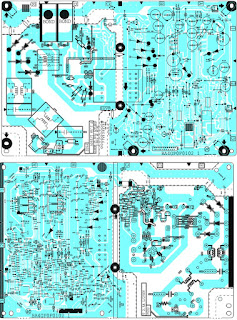
SMPS SCHEMATIC
Fixed Voltage (or Auto voltage selectable) power supply circuit is used in this unit.
If
Main Fuse (F602) is blown, first check to see that all components in
the power supply circuit are not defective before you connect the AC
plug to the AC power supply. Otherwise it may cause some components in
the power supply circuit to fail.


How to Remove / Install Flat Pack-IC
Removal
With Hot-Air Flat Pack-IC Desoldering Machine:
1. Prepare the hot-air flat pack-IC desoldering machine, then apply hot air to the Flat Pack-IC (about 5 to 6 seconds)
2. Remove the flat pack-IC with tweezers while applying the hot air.
3. Bottom of the flat pack-IC is fixed with glue to the CBA; when
removing entire flat pack-IC, first apply soldering iron to center of
the flat pack-IC and heat up. Then remove.
4. Release the flat pack-IC from the CBA using tweezers.
The Flat Pack-IC shape may differ by models. Use an appropriate
hot-air flat pack-IC desoldering machine, whose shape matches that of
the Flat Pack-IC.
Do not supply hot air to the chip parts around the flat pack-IC for
over 6 seconds because damage to the chip parts may occur. Put masking
tape around the flat pack-IC to protect other parts from damage.
3. The flat pack-IC on the CBA is affixed with glue, so be careful
not to break or damage the foil of each pin or the solder lands under
the IC when removing it.
With Soldering Iron:
1. Using desoldering braid, remove the solder from all pins of the
flat pack-IC. When you use solder flux which is applied to all pins of
the flat pack-IC, you can remove it easily.
2. Lift each lead of the flat pack-IC upward one by one, using a
sharp pin or wire to which solder will not adhere (iron wire). When
heating the pins, use a fine tip soldering iron or a hot air desoldering
machine.
3. Bottom of the flat pack-IC is fixed with glue to the CBA; when
removing entire flat pack-IC, first apply soldering iron to center of
the flat pack-IC and heat up. Then remove (glue will be melted).
4. Release the flat pack-IC from the CBA using tweezers.

With Iron Wire:
1. Using desoldering braid, remove the solder from all pins of the
flat pack-IC. When you use solder flux which is applied to all pins of
the flat pack-IC, you can remove it easily.
2. Affix the wire to a workbench or solid mounting point.
3. While heating the pins using a fine tip soldering iron or hot air
blower, pull up the wire as the solder melts so as to lift the IC leads
from the CBA contact pads.
4. Bottom of the flat pack-IC is fixed with glue to the CBA; when
removing entire flat pack-IC, first apply soldering iron to center of
the flat pack-IC and heat up. Then remove (glue will be melted).
5. Release the flat pack-IC from the CBA using tweezers.
[When using a soldering iron, care must be taken to ensure that the
flat pack-IC is not being held by glue. When the flat pack-IC is removed
from the CBA, handle it gently because it may be damaged if force is
applied.]

Installation
1. Using desoldering braid, remove the solder from the foil of each
pin of the flat pack-IC on the CBA so you can install a replacement flat
pack-IC more easily.
2. The “*” mark on the flat pack-IC indicates pin 1. Be sure this
mark matches the pin 1 on the PCB when positioning for installation.
Then presolder the four corners of the flat pack-IC.
3. Solder all pins of the flat pack-IC. Be sure that none of the pins have solder bridges.

HOW TO INITIALIZE THE LCD TV
The
purpose of initialization is to place the set in a new out of box
condition. The customer will be prompted to select a language and
program channels after the set has been initialized. To put the program
back at the factory-default, initialize the LCD TV using the following
procedure.
[Disconnect any device from the USB Port before you conduct on this procedure.]
TYPE – A
Turn the power on.
2. Enter the service mode.
- To cancel the service mode, press [Power ] button on the remote control unit.
3. Press [BACK] button to enter the Control Panel Key Confirmation Menu.
4. Press all buttons on the control panel.
5. Press [INFO] button to proceed with the self check mode.
6. Make sure to confirm the "INITIALIZED : OK" appears in the green screen.
7. Unplug the AC Cord and plug it back on again.
TYPE
B
Turn
the power on.
2. Enter the service mode.
- To cancel the service mode, press [Power ] button on the remote control unit.
3. Press [BACK] button to enter the Control Panel Key Confirmation Menu.
4. Press any button on the control panel.
5. Press [INFO] button to proceed with the self check mode.
6. Make sure to confirm the "INITIALIZED FINISH" appears in the green screen.
7. Unplug the AC Cord and plug it back on again.
White
Balance Adjustment
The
White Balance Adjustment should be performed when replacing the LCD Panel or
Digital Main CBA.
Purpose:
To mix red and blue beams correctly for pure white.
Symptom of Maladjustment: White becomes bluish or reddish.
Symptom of Maladjustment: White becomes bluish or reddish.
Operate
the unit for more than 30 minutes.
2. Enter the service mode.
3. Press [VOLUME DOWN] button three times on the remote control unit to select “Drive setting” mode. “Drive-” appears in the screen.
4. Set the color analyzer at the CHROMA mode and zero point calibration. Bring the optical receptor pointing at the center of the LCD-Panel.
[The
optical receptor must be set perpendicularly to the LCD Panel surface.]
5.
Press [3] button to select the “HDB” for High Drive Blue adjustment. (“HDB”
appears in the screen.)
6. Press [MENU] button. The internal Raster signal appears in the screen.
6. Press [MENU] button. The internal Raster signal appears in the screen.
(“Internal
(Single)” appears in the upper right of the screen)
7. Press [CHANNEL UP/DOWN] buttons to adjust the color temperature becomes 12000°K (x= 0.272 / y= 0.278 ± 0.003).
8.
Press [1] button to select the “HDR” for High Drive Red adjustment
(“HDR” appears in the screen.) and press [CHANNEL UP/DOWN] buttons to
adjust the color temperature.
9. If necessary, adjust the “HDB” or “HDR” again
10.
Press [6] button to select the “MDB” for Middle Drive Blue adjustment
(“MDB” appears in the screen.) and press [CHANNEL UP/DOWN] buttons to
adjust the color temperature.
11.
Press [4] button to select the “MDR” for Middle Drive Red adjustment
(“MDR” appears in the screen.) and press [CHANNEL UP/DOWN] buttons to
adjust the color temperature.
12. If necessary, adjust the “MDB” or “MDR” again.
13.
Press [9] button to select the “LDB” for Low Drive Blue adjustment
(“LDB” appears in the screen.) and press [CHANNEL UP/DOWN] buttons to
adjust the color temperature.

14.
Press [7] button to select the “LDR” for Low Drive Red adjustment (“LDR”
appears in the screen.) and press [CHANNEL UP/DOWN] buttons to adjust the color
temperature.
15. If necessary, adjust the “LDB” or “LDR” again.
16. Press [VOLUME DOWN] button to shift to the “Debugging Message” mode. If there is no message under “[WB]” section, this adjustment completes. If “Drive settings are NG. Retry again.” Is displayed, repeat above steps from 5. to 15. Then check “Debugging Message” again. If “Drive settings are NG. Retry again.” is displayed; replace the LCD Panel or Digital Main CBA.
17.
To cancel or to exit from the White Balance Adjustment, press [CH RETURN] or
[PREV CH] button
15. If necessary, adjust the “LDB” or “LDR” again.
16. Press [VOLUME DOWN] button to shift to the “Debugging Message” mode. If there is no message under “[WB]” section, this adjustment completes. If “Drive settings are NG. Retry again.” Is displayed, repeat above steps from 5. to 15. Then check “Debugging Message” again. If “Drive settings are NG. Retry again.” is displayed; replace the LCD Panel or Digital Main CBA.