
How to troubleshoot power supply problems – Sony EX2S/EX2WM Direct-View LCD Television Chassis: KDL46XBR10, KDL52XBR10
Power Supplies and ProtectionThe GB2 board receives AC input and provides a standby power source along with a switched supply to generate the necessary voltages used by the various circuits.
Since the media receiver and monitor function as separate devices, they contain their own power supplies and protection circuits. Both power supplies function in a similar manner in that standby power is generated to keep the media receiver and monitor in a “ready” state. The primary difference between the two is that the media receiver power supply also keeps the main switching supply active at all times. The monitor power supply contains an additional converter circuit to generate the necessary voltages to drive the LED back-lighting system.
Media Receiver Power
AC input is applied directly to bridge rectifier D6000 without a relay to interrupt power. The main switching supply is run constantly whenever AC power is applied, thus, providing a constant unregulated 12V source. This is necessary to provide constant power for the wireless module.
The constant unregulated 12V also provides the operating power for the standby power supply. A regulated 3.3V source is generated to provide power to the microprocessor on the BUB board along with constant power to the RF remote module.
Protection
Zener diode D6255 monitors the standby 3.3V for any over-voltage condition. Q6254, in conjunction with a current monitoring resistor monitors for excessive current levels within the standby supply circuits. If the OVP or LVP circuits are activated, Q6252 and Q6253 are turned on, creating a latch circuit. Q6250 and Q6251 function as an on/off switch to disable IC6250 in the standby supply. As long as the over current condition exists, the standby supply will remain turned off.
IC6400 functions as an AC detect circuit. If AC power is lost at the bridge rectifier or the main switching supply fails, the AC Off detect exiting at CN1003 pin 2 will go low. This is detected by TV Micro IC3002 on the BUB board. The shift registers in the CPU are cleared for a reliable re-start should the AC detect line return back to normal.

Monitor Power
Monitor power supply located on the GD1 board
used in the monitor. It is similar to power supplies found in most Sony
televisions. A dedicated standby switching regulator provides power for the
devices that must remain running constantly. A main switching supply is activated
at turn-on along with an additional inverter to supply power for the LED back-lights.

Standby Power
When in standby mode, the main relay RY6000 is open. AC power is applied to the bridge rectifier D6002 through current limit resistor R6002.
The PFC circuit is inactive at this time so the rectified 160V is distributed to the standby, primary and LED drive power supplies. Only the standby is functional at this time.
Regulated 3.3V is provided for the QTM board via CN6253 pin 3. An unregulated 15V source (PRI_VCC) is generated on the primary side of T6200 of the standby supply. This voltage is used to provide a power source to turn on the main relay and the primary switching supply.
Primary PowerWhen in standby mode, the main relay RY6000 is open. AC power is applied to the bridge rectifier D6002 through current limit resistor R6002.
The PFC circuit is inactive at this time so the rectified 160V is distributed to the standby, primary and LED drive power supplies. Only the standby is functional at this time.
Regulated 3.3V is provided for the QTM board via CN6253 pin 3. An unregulated 15V source (PRI_VCC) is generated on the primary side of T6200 of the standby supply. This voltage is used to provide a power source to turn on the main relay and the primary switching supply.
When the unit is turned on, a high command (3.3V) enters at CN6253 pin 1. This
high passes through inverter Q6350, photo coupler PH6301 and inverter Q6304 to
turn on switch Q6203. PRI_VCC is now available to turn on main relay RY6000,
the PFC circuit and the primary power supply.
The DC voltage exiting the PFC circuit rises to approximately 390V. The primary switching supply outputs a regulated 12V and unregulated 12V for the audio circuits which is sent to the QTM board.
The DC voltage exiting the PFC circuit rises to approximately 390V. The primary switching supply outputs a regulated 12V and unregulated 12V for the audio circuits which is sent to the QTM board.
LED Inverter
A dedicated switching supply is used to provide variable power for the
groups of series connected LED back-lights located along the lower edge
of the LCD panel. This power supply is turned on by a back-light on
command. Operation of this power supply is discussed by the previous
post here.
Protection
The GD1 board contains circuits to monitor temperature, voltage and
current conditions. The PFC circuit is monitored for excessive
temperature and voltage by IC6300. If either of these exceeds specified
limits, IC6300 pulls down the power on command, causing the main relay
to open along with stopping the PFC and primary supply.
If the regulated 12V source from the primary supply exceeds the
specified limit (15V), the latch circuit consisting of Q6251 and Q6253
is activated. This pulls down the power on command turning off the PFC
and primary supply as described in the previous paragraph.
The regulated 12V source is monitored by the QTM board. If this voltage
is lost, the unit will shut down and display groups of 5 blinks on the
power/standby LED. Activation of any of the protect circuits on the GD1
board will cause this symptom.

Troubleshooting
Power supply failures occurring in the media receiver or monitor will provide a diagnostics code via the POWER/STBY LED on the affected
device. In situations where a complete power supply failure occurs there will not be a diagnostics indicator. Figure below contains a troubleshooting flowchart to determine the cause of a No-Power condition in the media receiver of monitor.

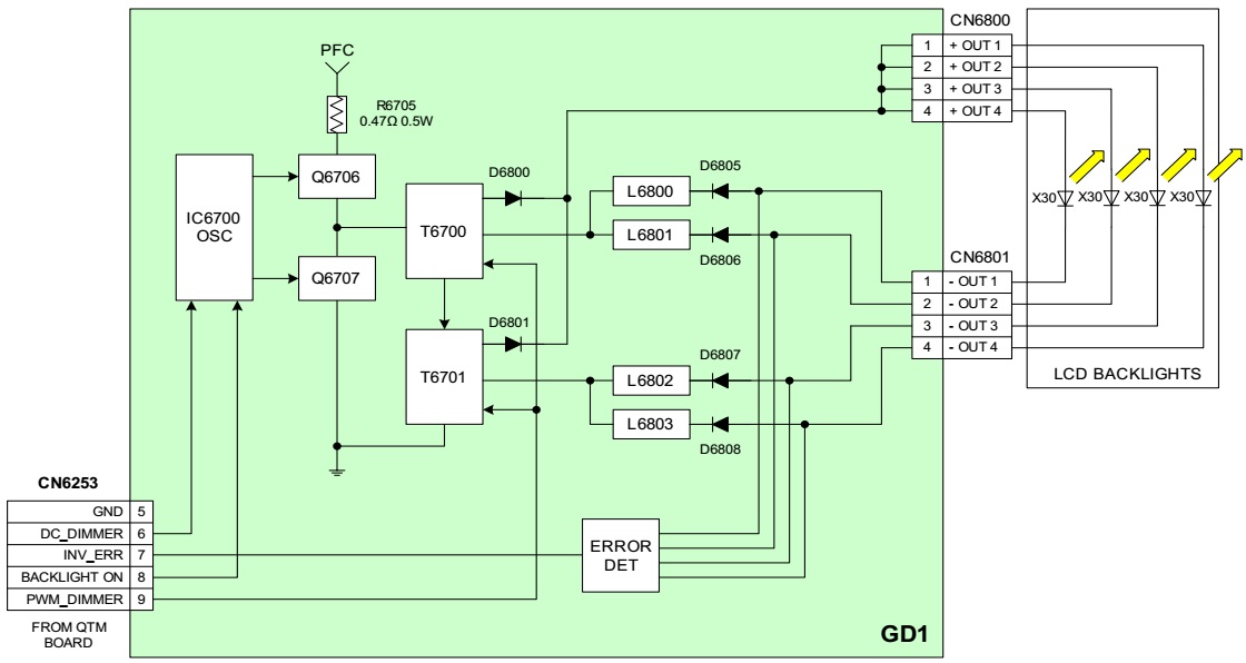
LED Back-light Drive
In Figure, the LED back-light power supply located on the GD1 board is
shown. IC6700 contains the oscillator and drive circuits for the switching transistors Q6706 and Q6707. The PFC 390V source provides drive
voltage to the switching circuit. T6700 and T6701 form a dual output switching
supply.
One common phase output from each transformer is tied together to form a single positive voltage. The remaining outputs are used to provide 2 negative voltage sources which are split to provide 2 sources each for a total of 4 negative supply voltages. 4 groups of series connected LED back-lights are driven from the positive side by the common +OUT voltage. Each of the 4 groups is driven by an individual –OUT voltage. The common +OUT voltage is fixed at approximately +49VDC referenced to chassis ground. The -OUT voltage level varies depending on the back-light level setting in the customer menu. The level of this voltage is controlled by the PWM_DIMMER line entering at CN6253 pin 9. The activity of this PWM line can be read with a DVM. The DC voltage level varies from approximately 2.7V at maximum back-light down to 0.34V at minimum back-light. The voltage range of the –OUT lines (referenced to chassis ground) is approximately -22VDC at minimum back-light to -45VDC at maximum level.
An additional dimming control source is available at pin 6 of CN6253. This is a DC dimming control and is primarily affected by the dynamic back-light control circuits which are monitoring relative video level of the displayed picture. The DC voltage at this line varies from 2.8V at maximum brightness to 0.96V at minimum.
Protection
The television will shut down and display a 6 blink error code on the POWER/STBY LED if the following faults occur:
Loss of PFC390 to the switching transistors (this is independentl (fused by R6705.)
A fault in the switching supply causing it to not turn on.
A loss of output from one or more of the –OUT lines.
A failure of one or more back-light LED’s in one of the series strings
Missing back-light on command