
Magnavox MWC24T5 Service mode and adjustments, SMPS circuit diagram - 24 inch COLOR CRT-TV/DVD/VCR
How
to enter service mode, adjustments, Power supply regulator board circuit
diagram, Magnavox MWC24T5 24 inch COLOR TV/DVD/VCR, Universal
remote control set-up code list for Magnavox brand TVs
When servicing the deck mechanism, refer to MK14 Deck Mechanism.
Deck Mechanism Part No.: N2466FT
The
MWC24T5 version B model, which is different from the previous model. For
MWC24T5 version B model, a suffix “B” is printed on the rating label on
the back of the unit. Refer to the rating label illustration.
How to make service remote control unit:
Prepare normal remote control unit (Part No. NE204UD or NE209UD).
* Remove 4 screws from the back lid.
* Remove the batteries.
* Cut off pin 10 of the remote control microprocessor and short circuit pins 10 and 17 of the microprocessor with a jumper wire.
* Insert the battery. The user remote control is now act as service remote control. After all service adjustments, and making the set to normal mode, Remove the battery again, and remove the short short circuit, re-solder the pin 10 to the circuit board. Insert the battery again, close the remote control. Now the remote control has turned to user remote control again.

How
to enter the Service mode:
1. Use the service remote control unit.
2. Turn the power on. (Use main power on the TV unit.)
3. To enter the TV mode, press [CH.Up/Dn] buttons on the TV unit.
4. Press [DISC MENU] button on the service remote control unit. Version of micro computer will display on the CRT. (Ex: BA4-0.16).
1. Use the service remote control unit.
2. Turn the power on. (Use main power on the TV unit.)
3. To enter the TV mode, press [CH.Up/Dn] buttons on the TV unit.
4. Press [DISC MENU] button on the service remote control unit. Version of micro computer will display on the CRT. (Ex: BA4-0.16).
X-Ray
Protection Test
X-Ray protection test should be done when replacing any parts of this chassis.
1. Short both ends of R2592 (on Sub CBA).
2. Confirm that the main power turns off.
3. If the main power does not turn off, then replace the following parts (D2591, Q2591, R2592, R2593, R2594 and IC1201).
4. Perform steps 1 to 3 again.
Setting for CONTRAST, COLOR,TINT, V-TINT and SHARP Data Values
1. Enter the Service mode.
2. Press [PICTURE] button on the service remote control unit.
Display changes “BRT,” “CNT,” “COL,” “TNT,” “V-T,” and “SHP” cyclically when [PICTURE] button is pressed.
CONTRAST
(CNT)
1. Press [PICTURE] button on the service remote control unit. Then select “CONTRAST (CNT)” display.
2. Press [CH.Up/Dn] buttons on the service remote control unit so that the value of “CONTRAST (CNT)” becomes 84.
1. Press [PICTURE] button on the service remote control unit. Then select “CONTRAST (CNT)” display.
2. Press [CH.Up/Dn] buttons on the service remote control unit so that the value of “CONTRAST (CNT)” becomes 84.
COLOR
(COL)
1. Press [PICTURE] button on the service remote control unit. Then select “COLOR (COL)” display.
2. Press [CH. Up/Dn] buttons on the service remote control unit so that the value of “COLOR (COL)” becomes 58.
1. Press [PICTURE] button on the service remote control unit. Then select “COLOR (COL)” display.
2. Press [CH. Up/Dn] buttons on the service remote control unit so that the value of “COLOR (COL)” becomes 58.
TINT
(TNT)
1. Press [PICTURE] button on the service remote control unit. Then select “TINT (TNT)” display.
2. Press [CH.Up/Dn] buttons on the service remote control unit so that the value of “TINT (TNT)” becomes 45.
1. Press [PICTURE] button on the service remote control unit. Then select “TINT (TNT)” display.
2. Press [CH.Up/Dn] buttons on the service remote control unit so that the value of “TINT (TNT)” becomes 45.
V-TINT
(V-T)
1. Press [PICTURE] button on the service remote control unit. Then select “V-TINT (V-T)” display.
2. Press [CH.Up/Dn] buttons on the service remote control unit so that the value of “V-TINT (V-T)” becomes 49.
1. Press [PICTURE] button on the service remote control unit. Then select “V-TINT (V-T)” display.
2. Press [CH.Up/Dn] buttons on the service remote control unit so that the value of “V-TINT (V-T)” becomes 49.
SHARP
(SHP)
1. Press [PICTURE] button on the service remote control unit. Then select “SHARP (SHP)” display.
2. Press [CH.Up/Dn] buttons on the service remote control unit so that the value of “SHARP (SHP)” becomes 46.
Note: BRIGHT data value does not need to be adjusted because this setting is performed in other setting.
H f0 Adjustment
Purpose: To get correct horizontal position and size of screen image.
Symptom of Misadjustment: Horizontal position and size of screen image may not be properly displayed.
1. Connect frequency counter to R2583.
2. Operate the unit for at least 20 minutes.
3. Enter the Service mode. Press [2] button on the remote control unit and select HADJ mode.
4. Press [CH.Up/Dn] buttons on the remote control unit so that the display will change “0” to “7.”
5. At this moment, choose display “0” to “7” when the frequency counter display is closest to 15.734 kHz 300 Hz.
Cut-off
Adjustment
Purpose: To adjust the beam current of R, G, B, and screen voltage.
Symptom of Misadjustment: White color may be reddish, greenish or bluish.
Purpose: To adjust the beam current of R, G, B, and screen voltage.
Symptom of Misadjustment: White color may be reddish, greenish or bluish.
1.
Degauss the CRT and allow the unit to operate for 20 minutes before starting
the alignment.
2. Input the Black raster signal from RF input.
3. Enter the Service mode.
2. Input the Black raster signal from RF input.
3. Enter the Service mode.
4.
Press the [VOL Dn] button. (Press [VOL Dn] button then display will change “C/D”, “7F” and Initial
Setting.)
5. Choose CUT OFF/DRIVE mode then press [1] button. This adjustment mode is CUT OFF (R).
6. Increase the screen control so that the horizontal line just appears on the CRT.
7. Press the [CH. Up/Dn] buttons until the horizontal line becomes white.
8. Choose CUT OFF/DRIVE mode then press [2] button. This adjustment mode is CUT OFF (G).
Press [CH.Up/Dn] buttons until the horizontal line becomes white.
9. Choose CUT OFF/DRIVE mode then press [3] button. This adjustment mode is CUT OFF (B).
Press [CH. Up/Dn] buttons until the horizontal line becomes white.
H. Size Adjustment
Purpose: To obtain correct size of screen image.
Symptom of Misadjustment: Size of screen image may not be properly displayed.
Note: VR2531 --- Sub CBA
1. Input monoscope pattern.
2. Adjust VR2531 so that the monoscope pattern is 90+1%/-5% of display size and the circle is round.
H. Pincushion Adjustment
Purpose: To obtain straight line on the screen.
Symptom of Misadjustment: Straight line image may not be properly displayed.
Note: VR2530 --- Sub CBA
1. Input crosshatch pattern.
2. Adjust VR2530 so that the lines of the crosshatch pattern become straight.
White
Balance Adjustment
Purpose: To mix red, green and blue beams correctly for pure white.
Symptom of Misadjustment: White becomes bluish or reddish.
Purpose: To mix red, green and blue beams correctly for pure white.
Symptom of Misadjustment: White becomes bluish or reddish.
Note:
Use service remote control unit
1. Operate the unit more than 20 minutes.
2. Face the unit to the east. Degauss the CRT using a degaussing coil.
3. Input the White Raster (APL 100%).
4. Set the color analyzer to the CHROMA mode and after zero point calibration; bring the optical receptor to the center on the tube surface (CRT).
5. Enter the Service mode. Press [VOL Dn] button on the service remote control unit and select “C/D” mode. (Display changes “C/D”, “7F” and Initial Setting cyclically when [VOL Dn] button is pressed.)
6. Press [4] button on the service remote control unit for Red adjustment. Press [5] button on the service remote control unit for Blue adjustment.
7. In each color mode, press [CH. Up/Dn] buttons to adjust the values of color.
8. Adjust Red and Blue color so that the temperature becomes 9200K (x: 286 / y: 294) ±3%.
9. At this time, re-check that horizontal line is white. If not, re-adjust Cut-off Adjustment until the horizontal line becomes pure white.
10. Turn off and on again to return to normal mode. Receive APL 100% white signal and confirm that Chroma temperatures become 9200K (x: 286 / y:294) ±3%.
Note: Confirm that Cut Off Adj. is correct after this adjustment, and attempt Cut Off Adj. if needed.
Sub-Brightness
Adjustment
Purpose: To get proper brightness.
Symptom of Misadjustment: If Sub-Brightness is incorrect, proper brightness cannot be obtained by adjusting the Brightness Control.
Purpose: To get proper brightness.
Symptom of Misadjustment: If Sub-Brightness is incorrect, proper brightness cannot be obtained by adjusting the Brightness Control.
Note:
SMPTE Setup level --- 7.5 IRE
1. Enter the Service mode. Then input SMPTE signal from RF input.
2. Press [PICTURE] button. (Press [PICTURE] button then display will change BRT, CNT, COL, TNT, V-T, and SHP). Select BRT and press [CH. Up/Dn] buttons so that the bar is just visible.
1. Enter the Service mode. Then input SMPTE signal from RF input.
2. Press [PICTURE] button. (Press [PICTURE] button then display will change BRT, CNT, COL, TNT, V-T, and SHP). Select BRT and press [CH. Up/Dn] buttons so that the bar is just visible.
Focus
Adjustment
Purpose: Set the optimum Focus.
Symptom of Misadjustment: If Focus Adjustment is incorrect, blurred images are shown on the display.
Purpose: Set the optimum Focus.
Symptom of Misadjustment: If Focus Adjustment is incorrect, blurred images are shown on the display.
Note:
Focus VR --- FBT (Sub CBA),
FBT = Fly Back Transformer
1. Operate the unit more than 30 minutes.
2. Face the unit to the East and degauss the CRT using a degaussing coil.
3. Input the monoscope pattern.
4. Adjust the Focus Control on the FBT to obtain a clear picture.
FBT = Fly Back Transformer
1. Operate the unit more than 30 minutes.
2. Face the unit to the East and degauss the CRT using a degaussing coil.
3. Input the monoscope pattern.
4. Adjust the Focus Control on the FBT to obtain a clear picture.
H.
Position Adjustment
Purpose: To obtain correct horizontal position of screen image.
Symptom of Misadjustment: H. position may not be properly displayed.
Purpose: To obtain correct horizontal position of screen image.
Symptom of Misadjustment: H. position may not be properly displayed.
1.
Enter the Service mode.
Press [8] button on the remote control unit and select H-P mode.
2. Input monoscope pattern.
3. Press [CH.Up/Dn] buttons on the remote control unit so that the left and right side of the monoscope pattern are equal to each other.
Press [8] button on the remote control unit and select H-P mode.
2. Input monoscope pattern.
3. Press [CH.Up/Dn] buttons on the remote control unit so that the left and right side of the monoscope pattern are equal to each other.
V.
Shift Adjustment
Purpose: To obtain correct vertical position of screen image.
Symptom of Misadjustment: If V. position is incorrect, vertical position of image on the screen may not be properly displayed.
Purpose: To obtain correct vertical position of screen image.
Symptom of Misadjustment: If V. position is incorrect, vertical position of image on the screen may not be properly displayed.
1.
Enter the Service mode.
Press [9] button on the remote control unit and select V-P mode. (Press [9] button then display will change to V-P and V-S).
2. Input monoscope pattern.
3. Press [CH.Up/Dn] buttons on the remote control unit so that the top and bottom of the monoscope pattern are equal to each other.
Press [9] button on the remote control unit and select V-P mode. (Press [9] button then display will change to V-P and V-S).
2. Input monoscope pattern.
3. Press [CH.Up/Dn] buttons on the remote control unit so that the top and bottom of the monoscope pattern are equal to each other.
V.
Size Adjustment
Purpose: To obtain correct vertical height of screen image.
Symptom of Misadjustment: If V. Size is incorrect, vertical height of image on the screen may not be properly displayed.
Purpose: To obtain correct vertical height of screen image.
Symptom of Misadjustment: If V. Size is incorrect, vertical height of image on the screen may not be properly displayed.
1.
Enter the Service mode.
Press [9] button on the remote control unit and select V-S mode. (Press [9] button then display will change to V-P and V-S).
2. Input monoscope pattern.
3. Press [CH. Up/Dn] buttons on the remote control unit so that the monoscope pattern is 905% of display size and the circle is round.
Press [9] button on the remote control unit and select V-S mode. (Press [9] button then display will change to V-P and V-S).
2. Input monoscope pattern.
3. Press [CH. Up/Dn] buttons on the remote control unit so that the monoscope pattern is 905% of display size and the circle is round.
Head
Switching Position Adjustment
Purpose: Determine the Head Switching Position during Playback.
Symptom of Misadjustment: May cause Head Switching Noise or Vertical Jitter in the picture.
Note: Unit reads Head Switching Position automatically and displays it on the screen (Upper Left Corner).
1. Playback test tape (VFMS0001H6).
2. Enter the Service mode.
Then press the number [5] button on the remote control unit.
3. The Head switching position will display on the screen; if adjustment is necessary follow step 4.
6.5H(412.7microseconds) is preferable.
4. Press [CH.Up] or [CH.Dn] button on the remote control unit if necessary. The value will be changed in 0.5H steps up or down. Adjustable range is up to 9.5H. If the value is beyond
adjustable range, the display will change as:
Lower out of range: 0.0H
Upper out of range: -.-H
The
following 2 adjustments normally are not attempted in the field. They
should be done only when replacing the CRT then adjust as a preparation.
Purity Adjustment
Purpose: To obtain pure color.
Symptom of Misadjustment: If Color Purity Adjustment is incorrect, large areas of color may not be properly displayed.
* This becomes RED COLOR if the [7] button is pressed while in service mode.
1. Set the unit facing east.
2. Operate the unit for over 30 minutes before adjusting.
3. Fully degauss the unit using an external degaussing coil.
4. Set the unit to the AUX mode which is located before CH2 then input a red raster from video in.
5. Loosen the screw on the Deflection Yoke Clamper and pull the Deflection Yoke back away from the screen.
6.
Loosen the Ring Lock and adjust the Purity Magnets so that a red field
is obtained at the center of the screen. Tighten Ring Lock.
7. Slowly push the Deflection Yoke toward the bell of the CRT and set it where a uniform red field is obtained.
8. Tighten the clamp screw on the Deflection Yoke.
Convergence
Adjustment
Purpose: To obtain proper convergence of red, green and blue beams.
Symptom of Misadjustment: If Convergence Adjustment is incorrect, the edge of white letters may have color edges.
Purpose: To obtain proper convergence of red, green and blue beams.
Symptom of Misadjustment: If Convergence Adjustment is incorrect, the edge of white letters may have color edges.
1. Set
the unit to the AUX mode which is located before CH2 then input a dot or
crosshatch pattern.
2. Loosen the Ring Lock and align red with blue dots or crosshatch at the center of the screen by rotating (RB) C.P. Magnets.
3. Align red / blue with green dots at the center of the screen by rotating (RB-G) C.P. Magnet.
2. Loosen the Ring Lock and align red with blue dots or crosshatch at the center of the screen by rotating (RB) C.P. Magnets.
3. Align red / blue with green dots at the center of the screen by rotating (RB-G) C.P. Magnet.
4.
Fix the C.P. Magnets by tightening the Ring Lock.
5. Remove the DY Wedges and slightly tilt the Deflection Yoke horizontally and vertically to obtain the best overall convergence.
6. Fix the Deflection Yoke by carefully inserting the DY Wedges between CRT and Deflection Yoke.
5. Remove the DY Wedges and slightly tilt the Deflection Yoke horizontally and vertically to obtain the best overall convergence.
6. Fix the Deflection Yoke by carefully inserting the DY Wedges between CRT and Deflection Yoke.
HOW
TO INITIALIZE THE TV/DVD/VCR
To
put the program back at the factory-default, initialize the TV/DVD/VCR as the
following procedure.
DVD Section
1. Turn the power on and press [SELECT] button on the remote control unit to put the TV/DVD/VCR into DVD mode.
2. Press [1], [2], [3], [4], and [DISPLAY] buttons on the remote control unit in that order.
3. Press [CLEAR] button on the remote control unit.
1. Turn the power on and press [SELECT] button on the remote control unit to put the TV/DVD/VCR into DVD mode.
2. Press [1], [2], [3], [4], and [DISPLAY] buttons on the remote control unit in that order.
3. Press [CLEAR] button on the remote control unit.
When
“OK” appears on the screen, the factory default will be set.
4. To exit this mode, press [CH. Up/Dn] or [SELECT] button to go to TV mode, or press [STANDBY-ON] button to turn the power off.
4. To exit this mode, press [CH. Up/Dn] or [SELECT] button to go to TV mode, or press [STANDBY-ON] button to turn the power off.

TV/VCR Section
1. Use the service remote control unit.
2. Turn the power on. (Use main power on the TV unit.)
3. Press [DISC MENU] button on the service remote control unit to enter the Service mode.
4.
Press [VOL Dn] button on the service remote control unit twice, and
confirm that OSD indication is “7F = FF.” If needed, set it to become
“7F = FF” by pressing [CH.Up/Dn] buttons on the service remote control
unit.
5.
Confirm that OSD indication on the four corners on TV screen changes
from on and off light indication to red by pressing a [DISPLAY] button.
(It is necessary for one or two seconds.)
6. Turn the power off by pressing main power button on the TV unit, and unplug the AC cord from the AC outlet.
FIRMWARE
RENEWAL MODE
1. Turn
the power on and press [SELECT] button on the remote control unit to put the
TV/DVD/VCR into DVD mode. Then remove the disc on the tray.
(It is possible to move to F/W version up mode only when the TV/DVD/VCR is in DVD mode with the tray open.)
2. To put the TV/DVD/VCR into F/W version up mode, press [9], [8], [7], [6], and [MODE] buttons on the remote control unit in that order.
(It is possible to move to F/W version up mode only when the TV/DVD/VCR is in DVD mode with the tray open.)
2. To put the TV/DVD/VCR into F/W version up mode, press [9], [8], [7], [6], and [MODE] buttons on the remote control unit in that order.
The
TV/DVD/VCR can also enter the version up mode with the tray open. In this case,
Fig. will be shown on the screen while
the tray is open.
3. Load the disc for version up.
4. The TV/DVD/VCR enters the F/W version up mode automatically. Fig. appears on the screen.
If you enter the F/W for different models, “Disc Error” will appear on the screen, and then the tray will open automatically.
3. Load the disc for version up.
4. The TV/DVD/VCR enters the F/W version up mode automatically. Fig. appears on the screen.
If you enter the F/W for different models, “Disc Error” will appear on the screen, and then the tray will open automatically.

5. After programming is finished, the tray opens automatically. And the checksum will be shown.
At this time, no button is available.
6. Remove the disc on the tray.
7.
Press [SELECT] button on the remote control unit to go to TV mode, or
press [STANDBY-ON] button on the unit to turn the power off.
8. Press [SELECT] button on the remote control unit to put the TV/DVD/VCR into DVD mode again.
9. Press [1], [2], [3], [4], and [DISPLAY] buttons on the remote control unit in that order.
10. Press [CLEAR] button on the remote control unit.

When
“OK” appears on the screen, the factory default will be set. Then the firmware
renewal mode is complete.
11. To exit this mode, press [CH. Up/Dn] or [SELECT] button to go to TV mode, or press [STANDBY-ON] button to turn the power off.
11. To exit this mode, press [CH. Up/Dn] or [SELECT] button to go to TV mode, or press [STANDBY-ON] button to turn the power off.
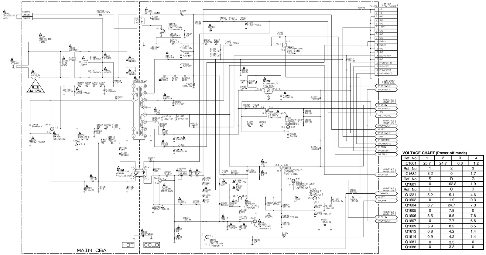
SMPS circuit diagram
CAUTION:
Fixed Voltage (or Auto voltage selectable) power supply circuit is used in this
unit.
If Main Fuse (F1601) is blown, first check to see that all components in the power supply circuit are not defective before you connect the AC plug to the AC power supply. Otherwise it may cause some components in the power supply circuit to fail.
If Main Fuse (F1601) is blown, first check to see that all components in the power supply circuit are not defective before you connect the AC plug to the AC power supply. Otherwise it may cause some components in the power supply circuit to fail.
Universal remote control set-up codes to check with Magnavox Brand Televisions
0018 0042 0049 0101 0152 0680