NXP TDA9351/53/61/63 XXX SERIES – Color TV – Memory IC replacement, IC Pin voltages and functions, Service mode and adjustments, default data values, Full schematic and more….
TDA9351, TDA8370, TDA9353, OM8370 – IC
default data and functional description. Schematic (full): Used ICs –
TDA9341, CD4052, AT24C08, AN7522, TDA2003, [BSC25 N0832 / BSC25 T1010A /
BSC24 01N4014K Flyback Transformer], [D1651 / TT2190 – Horizontal
Output Transistor], LA78040(Vertical scan output IC), [21-inch-2SC5287/
29-inch-2AC5297 – SMPS switching transistor]

1. MEMORY IC.
This TV uses memory IC. In the memory IC are memorized data for correctly operating the video and deflection circuits. When replacing memory IC, be sure to use IC written with the initial value of data.
2. PROCEDURE FOR REPLACING MEMORY IC
(1) Power off
Switch the power off and unplug the power cord from AC outlet.
(2) Replace IC
Be sure to use memory IC written with the initial data values.
(3) Power On
Plug the power cord into the AC outlet and switch the power On.
(4) Check and set system default value:
1) Press “MENU” key followed by digits '6''4''8' and '3'. then Press “TEST” key on the Remote control unit for factory used.
2) The red “M”or”factory” will be displayed on the screen, repeat this and it will changed as follow:
normal-M(factory)-BUS open-normal..
3) Press digital key, (Mkey) and corresponding on-screen display will be appeared.
4) Check the setting value of the SYSTEM default value of Table below. If the value is different, select items by [CH+]/[CH-] keys and set value by [VOL+]/[VOL-] keys.
5) Press “STANDBY” key again and return to the normal screen.
SERVICE
ADJUSTMENT
B1 POWER SUPPLY
1. Receive normal colour bar signal.
2. Connect DC voltmeter to VD524- and isolated ground.
3. Adjust potentiometer in power unit to get the voltage as 110V ±1.0V for 21 inch hereinafter, FOCUS ADJUSTMENT
1. Receive a crosshatch signal.
2. While watching the screen, adjust the FOCUS VR to make the vertical and horizontal lines as fine and sharp as possible.
BUS CONTROL ADJUSTMENT
TDA9351/9353: To enter BUS control mode, Press “MENU” key followed by digits '6''4''8' and '3'. Then press digit Press “0” to “9“ key, (Mkey) and corresponding on-screen display will be appeared.
TDA8370: To enter BUS control mode, Press “MENU” key followed by digits '6''4''8' and '3'. then Press “TEST” key on the Remote control unit twice for factory used(or press digits '6''4''8' and '3' twice.). and then press digit Press “0” to “9“ key, (Mkey) and corresponding on-screen display will be appeared.
On TV screen “TEST” will be indicated, this means entered bus control mode.
And press following key, each function will be available.
Remote Hand Unit keys

Geometrical adjustment
MENU8 (9351)/servise 1(8370)
Receive PAL standard Complete pattern signal.
Adjustment steps
a) Adjust V. SLOPE, to the center horizontal line just appeare from half bottom shadow.
b) Adjust V. SIZE, to get 90% of vertical picture contents would be displayed on CRT.
c) Adjust V. SHIFT, the center horizontal line correspond to CRT vertical center.
d) Adjust H.SHIFT, to get the picture horizontal center correspond to CRT horizontal center.
Receive NTSC signal and repeat above.
AGC Adjustment.
MENU7 (9351)/servise 2(8370)
Receive
60dBμ(1mV)VH colour bar pattern signal,adjust AGC value(voltage from
high to low),to noise reduce gradually and just disappeared point.
CRTcut off and white balance adjustment.
MENU9 (9351)/B W BALANCE(8370)
Receive white signal.
a) CRT cut off adjustment.
1. Select “SC”, then automatically vertical scan will be stopped.
2. Adjust
SCREEN control on Flyback transformer to get the darkest single
horizontal line (red, green, or blue, sometimes shows more yellow, more
purple or more white).
b) White balance adjustment.
1. Select RD/BD menu.
2. Adjust RD/BD to get colour temperature as x=281, y=311
c) Sub-Brightness adjustment. (Use stair case signal)
1. Select SB menu.
2. Adjust SB to get the darkest step being cutoff.
DEFAULT DATA SETTING VALUES

AV OPTION:MENU1→AV CFG;
O =TV→AV;1=TV→AV1→AV2;2=TV→AV1→AV2→S-VIDEO;3=TV→AV1→AV2→S-VIDEO→YUV;
5 = TV→AV→S-VIDEO;6= TV→AV→S-VIDEO→YUV;7= TV→AV→YUV;8=TV→EURO;
9 =TV→AV→EURO

OM8370
– White balance
Note
1. The function of pin 20, 28, 29, 31, 32, 35 and 44 is dependent on the
IC version (mono intercarrier FM demodulator /QSS IF amplifier and
East-West output or not) and on some software control bits. The valid
combinations are given in table 1. [Below]
2. the vertical guard function can be controlled via pin 49 or pin 50.
the selection is made by means of the IVG bit in subaddress 2BH.
Note
1. When additional (external) selectivity is required for FM-PLL system pin 32 can be used as sound IF input.
This function is selected by means of SIF bit in subaddress 28H.
2. the reference output signal is only available for the CMB1/CMB0
setting of 0/1. for the other settings this pin is a switch output(see
also 5 table 67). [below]


Test
point waveforms

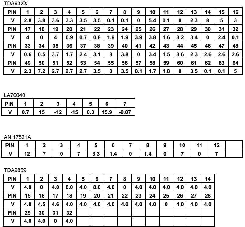
IC
pin voltages
Full circuit diagram / Schematic and PWB


Click on the pictures to magnify