How to enter the service mode – JVC LT26WX84 NTSC LCD TV, adjustments, SMPS schematic
JVC
LT-26WX84/T LCD FLAT TELEVISION SB5 CHASSIS.
TV RF System- CCIR (M); Color System- NTSC; Sound System- BTSC (Multi
Channel Sound)
PIXEL
FAULT
There are three pixel faults - bright fault , dark fault and flicker fault - that are respectively defined as follows.
(1) BRIGHT FAULT
In this pixel fault, a cell that should not light originally is lighting on and off.
For checking this pixel fault, input ALL BLACK SCREEN and find out the cell that is lighting on and off.
(2) DARK FAULT
In this pixel fault, a cell that should light originally is not lighting or lighting with the brightness twice as brighter as originally lighting.
For checking this pixel fault, input 100% of each R/G/B colour and find out the cell that is not lighting.
(3) FLICKER FAULT
In the pixel fault, a cell that should light originally or not light originally is flashing on and off.
For checking this pixel fault, input ALL BLACK SCREEN signal or 100% of each RGB colour and find out the cell that is flashing on and off
 REMOVING
THE MI-COM & DIST MODULE PWB
REMOVING
THE MI-COM & DIST MODULE PWB• Remove the STAND.
• Remove the REAR COVER.
• DIGITAL INPUT MODULE PWB
(1) Remove the 7 screws [T], and remove the VIDEO PWB BRACKET.
(2) Remove the 4 screws [U], and remove the MI-COM & DIST MODULE PWB from the VIDEO PWB BRACKET.

MEMORY
IC REPLACEMENT
This memory IC stores data for proper operation of the video and deflection circuits.
When replacing, be sure to use an IC containing this (initial value) data.
MEMORY
IC REPLACEMENT PROCEDUREThis memory IC stores data for proper operation of the video and deflection circuits.
When replacing, be sure to use an IC containing this (initial value) data.
(1) Power off
Switch off the power and disconnect the power cord from the wall outlet.
(2) Replace the memory IC
Initial value must be entered into the new IC.
(3) Power on
Connect the power cord to the wall outlet and switch on the power.
(4) SERVICE MODE setting
Before entering the SERVICE MODE, confirm that the setting of TV/CATV SW of the REMOTE CONTROL UNIT is at the "TV" side and the setting of VCR/DVD SW of the REMOTE CONTROL UNIT is at the "VCR" side. If the switches have not been properly set, you cannot enter the SERVICE MODE.
a) Press [SLEEP TIMER] key and, while the indication of SLEEP TIMER 0 MIN is being displayed, press [DISPLAY] key and [VIDEO STATUS] key on the remote control unit simultaneously.
b) The SERVICE MODE screen is displayed.
c) Verify what to set in the SERVICE MODE, and set whatever is necessary. Refer to the SERVICE ADJUSTMENT for setting.
d) Press the [BACK] key twice to return normal screen.
(5) Receive channel setting
Refer to the OPERATING INSTRUCTIONS (USER'S GUIDE) and set the receive channels (Channels Preset) as described.
(6) User settings
Check the user setting items according to after page.
Where these do not agree, refer to the OPERATING INSTRUCTIONS (USER'S GUIDE) and set the items as described.

REMOTE
CONTROL MENU OPERATION
(1) PICTURE ADJUSTMENT
Customers can adjust the picture setting of menu screen as their own like but the picture standard value during factory shipment is as below.
(1) PICTURE ADJUSTMENT
Customers can adjust the picture setting of menu screen as their own like but the picture standard value during factory shipment is as below.

HOW
TO ENTER THE SERVICE MODE
NOTE:
Ensure that the cursor (arrow) of the User Menu screen is pointing at Picture Control.
Before entering the SERVICE MODE, confirm that the setting of TV / CATV switch of the REMOTE CONTROL UNIT is at the "TV" side and the setting of VCR / DVD switch is at the "VCR" side. If the switches have not been properly set, you cannot enter the SERVICE MODE.
(1) Set to 0 minutes using the [SLEEP TIMER] key.
(2) Press the [VIDEO STATUS] key and [DISPLAY] key simultaneously, then enter the SERVICE MODE mode.
(3) When the Main Menu is displayed, press any key of the [0] to [9] key to enter the corresponding menu mode.
*Press any of the [0] to [9] keys before the SERVICE MODE mode disappears.
(4) Select the service item using the [ CH + ] / [ CH - ] key.
(5) Set the value using the [ VOL + ] / [ VOL - ] key.
(6) Press the [MUTING] key to save the value.
HOW
TO EXIT THE SERVICE MODE
Press the [ BACK ] key to exit the Service mode.
Press the [ BACK ] key to exit the Service mode.
BASIC
OPERATION OF SERVICE MODE
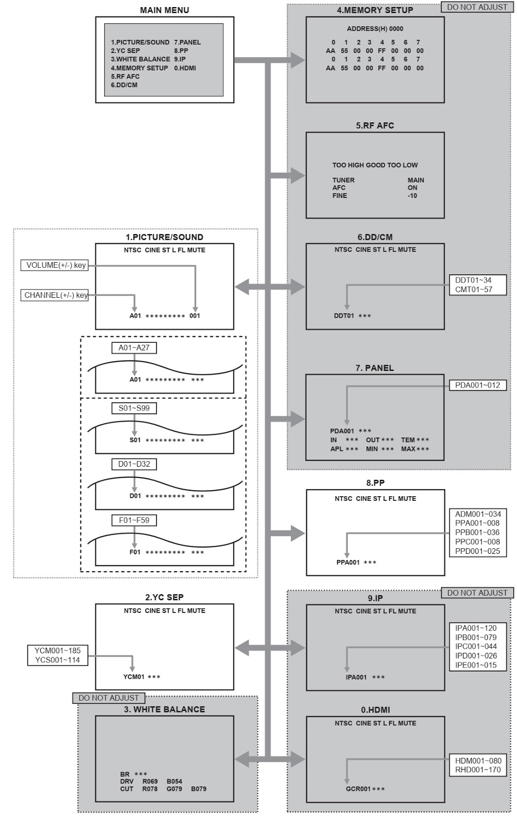
SERVICE
MODE ITEMS
In general, basic setting (adjustments) items or verifications are performed in the SERVICE MODE
In general, basic setting (adjustments) items or verifications are performed in the SERVICE MODE

HOW
TO ENTER THE SELF-DIAGNOSIS DISPLAY MODE
Before entering the Self-diagnosis Display mode, confirm that the setting of TV / CATV SW of the REMOTE CONTROL UNIT is at the "TV" side and the setting of VCR / DVD SW is at the "VCR" side. If the switches have not been properly set, you cannot enter the Self-diagnosis Display mode.
(1) Press the [SLEEP TIMER] key and set it to 30 minutes.
(2) Press the [VIDEO STATUS] key and [DISPLY] key simultaneously, then enter the TEST MODE.
(3) Press the [4] key (Self-diagnosis Display mode) before the service mode screen disappears.
(4) Press the [MTS] key to enter Page 2 of the Self-diagnosis Display mode.
*Use the [MTS] key to toggle between Page 1 and Page 2.
NOTE:
The remote control unit attached to this set does not contain the [MTS] key. To perform the procedure (4), use a remote control unit that contains the [MTS] key.
HOW
TO EXIT THE SELF-DIAGNOSIS DISPLAY MODEBefore entering the Self-diagnosis Display mode, confirm that the setting of TV / CATV SW of the REMOTE CONTROL UNIT is at the "TV" side and the setting of VCR / DVD SW is at the "VCR" side. If the switches have not been properly set, you cannot enter the Self-diagnosis Display mode.
(1) Press the [SLEEP TIMER] key and set it to 30 minutes.
(2) Press the [VIDEO STATUS] key and [DISPLY] key simultaneously, then enter the TEST MODE.
(3) Press the [4] key (Self-diagnosis Display mode) before the service mode screen disappears.
(4) Press the [MTS] key to enter Page 2 of the Self-diagnosis Display mode.
*Use the [MTS] key to toggle between Page 1 and Page 2.
NOTE:
The remote control unit attached to this set does not contain the [MTS] key. To perform the procedure (4), use a remote control unit that contains the [MTS] key.
To Save Failure History:
Turn off the power by unplugging the AC power cord plug when in the self-diagnosis display mode.
To Clear (Reset) Failure History:
Turn off the power by pressing the [POWER] key on the remote control unit when in the self-diagnosis display mode
Turn off the power by unplugging the AC power cord plug when in the self-diagnosis display mode.
To Clear (Reset) Failure History:
Turn off the power by pressing the [POWER] key on the remote control unit when in the self-diagnosis display mode
FAILURE
HISTORY
Failure history can be counted up to 9 times for each item. When the number exceeds 9, display will remain. Failure history will be stored in the memory unless it has been deleted.
NOTE:
Only SYNC (with/without sync signals) will be neither counted nor stored. POINTS TO NOTE WHEN USING THE SELF-DIAGNOSIS FEATURE
In addition to circuit failures (abnormal operation), the following cases may also be diagnosed as "Abnormal" and displayed and counted as "NG".
(1) Temporary defective transmissions across circuits due to pulse interruptions
(2) Misalignment in the on/off timing of power for I2C bus (VCC) when turning on/off the main power.
Diagnosis may be impeded if a large number of items are displayed as "NG". As such, start self-diagnosis check only after 3 seconds in the case of receivers and 5 seconds in the case of panels upon turning on the power. If recurrences are expected, ensure to clear (reset) the failure history and record the new diagnosis results.

DISPLAY
METHOD WHEN RASTER IS NOT AVAILABLE
When raster is not displayed due to failure of the set, the POWER LED light will flash to indicate the failure mode. Trigger for forced shutdown of power is stored and displayed.
When raster is not displayed due to failure of the set, the POWER LED light will flash to indicate the failure mode. Trigger for forced shutdown of power is stored and displayed.
Details
on Operation
Power of TV will be turned off when NG is detected for LOW B short Protection". "POWER LED" will start flashing immediately after power is turned off and power of tuner and panel cannot be turned on upon shutdown until the AC plugs are disconnected once and reconnected.
Power of TV will be turned off when NG is detected for LOW B short Protection". "POWER LED" will start flashing immediately after power is turned off and power of tuner and panel cannot be turned on upon shutdown until the AC plugs are disconnected once and reconnected.
REMOVING
THE POWER PWB
• Remove the STAND.
• Remove the REAR COVER.
• Remove the FAN BRACKET.
• Remove the POWER CORD.
• Remove the RECEIVER PWB.
(1) Remove the 4 screws [X], and remove the AV JACK BRACKET.
(2) Remove the 6 screws [Y], and remove the POWER PWB.
(3) Remove the 6 screws [Z], and remove the CHASSIS BASE
• Remove the STAND.
• Remove the REAR COVER.
• Remove the FAN BRACKET.
• Remove the POWER CORD.
• Remove the RECEIVER PWB.
(1) Remove the 4 screws [X], and remove the AV JACK BRACKET.
(2) Remove the 6 screws [Y], and remove the POWER PWB.
(3) Remove the 6 screws [Z], and remove the CHASSIS BASE

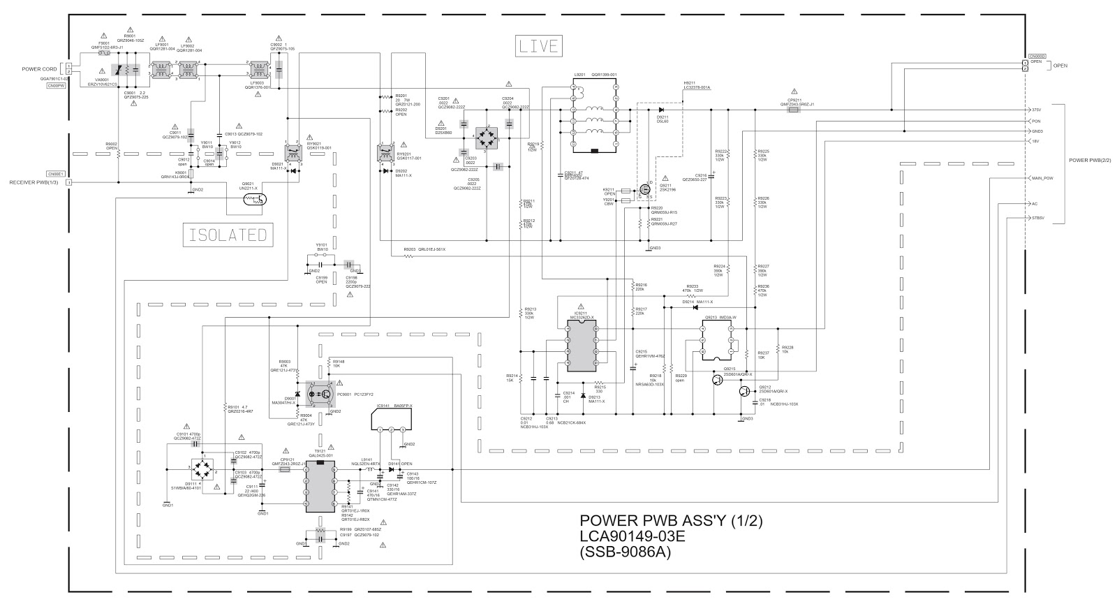
SMPS SCHEMATIC [Circuit diagram]

REMOVING
THE BACKLIGHT UNIT
NOTE:
Do not carry out the following procedure in a dusty and dirty place.
If the surface of LCD GLASS, the surface of DIFFUSER SHEET, and the inside of BACKLIGHT UNIT are dusty or dirty, they cause unevenness of a displayed screen.
• Remove the CONTROL PWB.
• Remove the INVERTER PWB.
• Place the LCD UNIT with the screen facing upward.
Remove
the 8 screws, 4screws, and 4 screws (16 screws in total), and
remove the MAIN CHASSIS.
NOTE: Be careful not to damage the SOURCE IC and the GATE IC on the side of LCD GLASS when removing the MAIN CHASSIS.
(2) Remove the 6 screws from the top side of the LCD UNIT.
(3) Remove the 12 screws from the sides of the LCD UNIT. Then, LCD GLASS, DIFFUSER SHEET, and BACKLIGHT UNIT are removed.
NOTE: Be careful not to damage the SOURCE IC and the GATE IC on the side of LCD GLASS when removing the MAIN CHASSIS.
(2) Remove the 6 screws from the top side of the LCD UNIT.
(3) Remove the 12 screws from the sides of the LCD UNIT. Then, LCD GLASS, DIFFUSER SHEET, and BACKLIGHT UNIT are removed.
Universal remote control set-up
codes for JVC TVs.
If your TV need a 3
digit code, delete the leading Zero, from each of the code said below, and then
check.
Set-up procedure of different
brand remote controls will not be the same.
You have to refer the user manual of that remote control to know more
about it.